With simple series circuits, all components are connected end-to-end to form only one path for electrons to flow through the circuit:
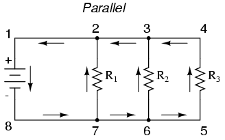
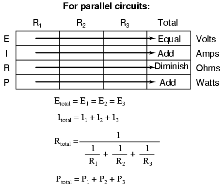
With simple parallel circuits, all components are connected between the same two sets of electrically common points, creating multiple paths for electrons to flow from one end of the battery to the other:
With each of these two basic circuit configurations, we have specific sets of rules describing voltage, current, and resistance relationships.
Series Circuits:
Voltage drops add to equal total voltage.
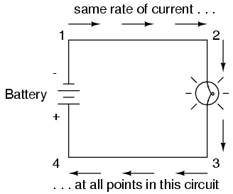
All components share the same (equal) current.
Resistances add to equal total resistance.
Parallel Circuits:
All components share the same (equal) voltage.
Branch currents add to equal total current.
Resistances diminish to equal total resistance.
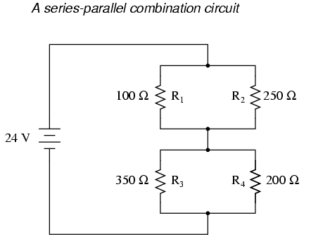
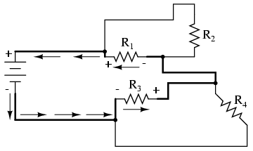
However, if circuit components are series-connected in some parts and parallel in others, we won’t be able to apply a single set of rules to every part of that circuit. Instead, we will have to identify which parts of that circuit are series and which parts are parallel, then selectively apply series and parallel rules as necessary to determine what is happening. Take the following circuit, for instance:
This circuit is neither simple series nor simple parallel. Rather, it contains elements of both. The current exits the bottom of the battery, splits up to travel through R3 and R4, rejoins, then splits up again to travel through R1 and R2, then rejoins again to return to the top of the battery. There exists more than one path for current to travel (not series), yet there are more than two sets of electrically common points in the circuit (not parallel).
Because the circuit is a combination of both series and parallel, we cannot apply the rules for voltage, current, and resistance “across the table” to begin analysis like we could when the circuits were one way or the other. For instance, if the above circuit were simple series, we could just add up R1 through R4 to arrive at a total resistance, solve for total current, and then solve for all voltage drops. Likewise, if the above circuit were simple parallel, we could just solve for branch currents, add up branch currents to figure the total current, and then calculate total resistance from total voltage and total current. However, this circuit’s solution will be more complex.
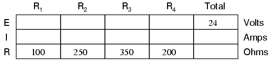
The table will still help us manage the different values for series-parallel combination circuits, but we’ll have to be careful how and where we apply the different rules for series and parallel. Ohm’s Law, of course, still works just the same for determining values within a vertical column in the table.
If we are able to identify which parts of the circuit are series and which parts are parallel, we can analyze it in stages, approaching each part one at a time, using the appropriate rules to determine the relationships of voltage, current, and resistance. The rest of this chapter will be devoted to showing you techniques for doing this.
REVIEW:
The rules of series and parallel circuits must be applied selectively to circuits containing both types of interconnections.
Analysis Techniques
The goal of series-parallel resistor circuit analysis is to be able to determine all voltage drops, currents, and power dissipations in a circuit. The general strategy to accomplish this goal is as follows:
Step 1: Assess which resistors in a circuit are connected together in simple series or simple parallel.
Step 2: Re-draw the circuit, replacing each of those series or parallel resistor combinations identified in step 1 with a single, equivalent-value resistor. If using a table to manage variables, make a new table column for each resistance equivalent.
Step 3: Repeat steps 1 and 2 until the entire circuit is reduced to one equivalent resistor.
Step 4: Calculate total current from total voltage and total resistance (I=E/R).
Step 5: Taking total voltage and total current values, go back to last step in the circuit reduction process and insert those values where applicable.
Step 6: From known resistances and total voltage / total current values from step 5, use Ohm’s Law to calculate unknown values (voltage or current) (E=IR or I=E/R).
Step 7: Repeat steps 5 and 6 until all values for voltage and current are known in the original circuit configuration. Essentially, you will proceed step-by-step from the simplified version of the circuit back into its original, complex form, plugging in values of voltage and current where appropriate until all values of voltage and current are known.
Step 8: Calculate power dissipations from known voltage, current, and/or resistance values.
This may sound like an intimidating process, but its much easier understood through example than through description.
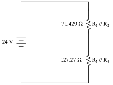
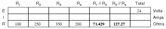
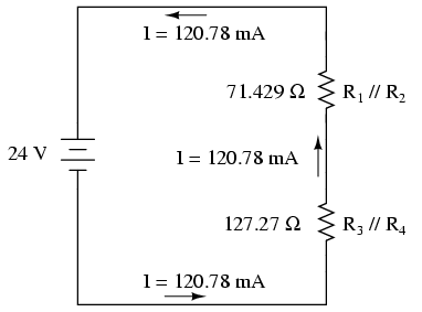
In the example circuit above, R1 and R2 are connected in a simple parallel arrangement, as are R3 and R4. Having been identified, these sections need to be converted into equivalent single resistors, and the circuit re-drawn:
The double slash (//) symbols represent “parallel” to show that the equivalent resistor values were calculated using the 1/(1/R) formula. The 71.429 Ω resistor at the top of the circuit is the equivalent of R1 and R2 in parallel with each other. The 127.27 Ω resistor at the bottom is the equivalent of R3 and R4 in parallel with each other.
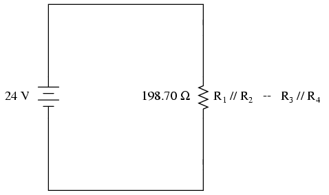
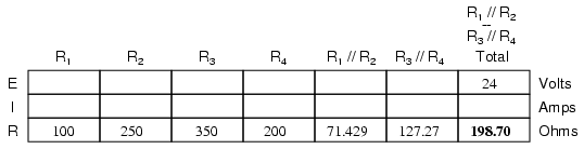
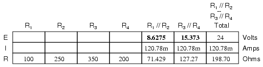
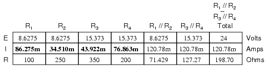
Our table can be expanded to include these resistor equivalents in their own columns:
It should be apparent now that the circuit has been reduced to a simple series configuration with only two (equivalent) resistances. The final step in reduction is to add these two resistances to come up with a total circuit resistance. When we add those two equivalent resistances, we get a resistance of 198.70 Ω. Now, we can re-draw the circuit as a single equivalent resistance and add the total resistance figure to the rightmost column of our table. Note that the “Total” column has been relabeled (R1//R2–R3//R4) to indicate how it relates electrically to the other columns of figures. The “–” symbol is used here to represent “series,” just as the “//” symbol is used to represent “parallel.”
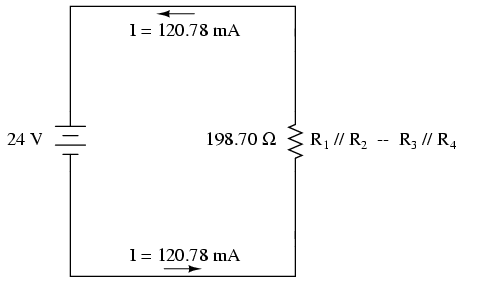
Now, total circuit current can be determined by applying Ohm’s Law (I=E/R) to the “Total” column in the table:
Back to our equivalent circuit drawing, our total current value of 120.78 milliamps is shown as the only current here:
Now we start to work backwards in our progression of circuit re-drawings to the original configuration. The next step is to go to the circuit where R1//R2 and R3//R4 are in series:
Since R1//R2 and R3//R4 are in series with each other, the current through those two sets of equivalent resistances must be the same. Furthermore, the current through them must be the same as the total current, so we can fill in our table with the appropriate current values, simply copying the current figure from the Total column to the R1//R2 and R3//R4 columns:
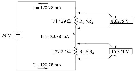
Now, knowing the current through the equivalent resistors R1//R2 and R3//R4, we can apply Ohm’s Law (E=IR) to the two right vertical columns to find voltage drops across them:
Because we know R1//R2 and R3//R4 are parallel resistor equivalents, and we know that voltage drops in parallel circuits are the same, we can transfer the respective voltage drops to the appropriate columns on the table for those individual resistors. In other words, we take another step backwards in our drawing sequence to the original configuration, and complete the table accordingly:
Finally, the original section of the table (columns R1 through R4) is complete with enough values to finish. Applying Ohm’s Law to the remaining vertical columns (I=E/R), we can determine the currents through R1, R2, R3, and R4 individually:
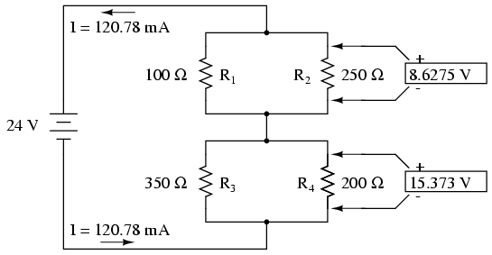
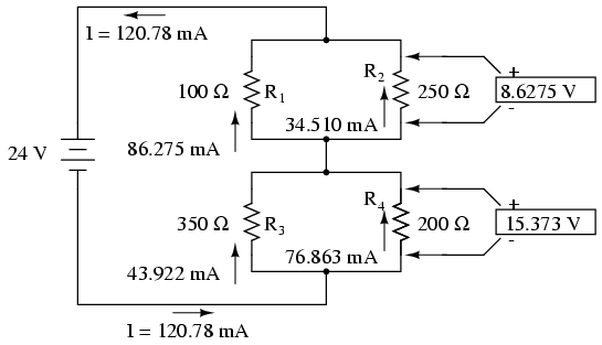
Having found all voltage and current values for this circuit, we can show those values in the schematic diagram as such:
As a final check of our work, we can see if the calculated current values add up as they should to the total. Since R1 and R2 are in parallel, their combined currents should add up to the total of 120.78 mA. Likewise, since R3 and R4 are in parallel, their combined currents should also add up to the total of 120.78 mA. You can check for yourself to verify that these figures do add up as expected.
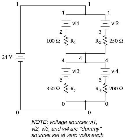
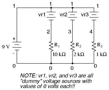
A computer simulation can also be used to verify the accuracy of these figures. The following SPICE analysis will show all resistor voltages and currents (note the current-sensing vi1, vi2, . . . “dummy” voltage sources in series with each resistor in the netlist, necessary for the SPICE computer program to track current through each path). These voltage sources will be set to have values of zero volts each so they will not affect the circuit in any way.
series-parallel circuit
v1 1 0
vi1 1 2 dc 0
vi2 1 3 dc 0
r1 2 4 100
r2 3 4 250
vi3 4 5 dc 0
vi4 4 6 dc 0
r3 5 0 350
r4 6 0 200
.dc v1 24 24 1
.print dc v(2,4) v(3,4) v(5,0) v(6,0)
.print dc i(vi1) i(vi2) i(vi3) i(vi4)
.end
I’ve annotated SPICE’s output figures to make them more readable, denoting which voltage and current figures belong to which resistors.
v1            v(2,4)      v(3,4)      v(5)        v(6)
2.400E+01     8.627E+00   8.627E+00   1.537E+01   1.537E+01
Battery       R1 voltage  R2 voltage  R3 voltage  R4 voltage
voltage
v1            i(vi1)      i(vi2)      i(vi3)      i(vi4)
2.400E+01     8.627E-02   3.451E-02   4.392E-02   7.686E-02
Battery       R1 current  R2 current  R3 current  R4 current
voltage
As you can see, all the figures do agree with the our calculated values.
REVIEW:
To analyze a series-parallel combination circuit, follow these steps:
Reduce the original circuit to a single equivalent resistor, re-drawing the circuit in each step of reduction as simple series and simple parallel parts are reduced to single, equivalent resistors.
Solve for total resistance.
Solve for total current (I=E/R).
Determine equivalent resistor voltage drops and branch currents one stage at a time, working backwards to the original circuit configuration again.
Re-drawing Complex Schematics
Typically, complex circuits are not arranged in nice, neat, clean schematic diagrams for us to follow. They are often drawn in such a way that makes it difficult to follow which components are in series and which are in parallel with each other. The purpose of this section is to show you a method useful for re-drawing circuit schematics in a neat and orderly fashion. Like the stage-reduction strategy for solving series-parallel combination circuits, it is a method easier demonstrated than described.
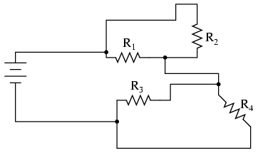
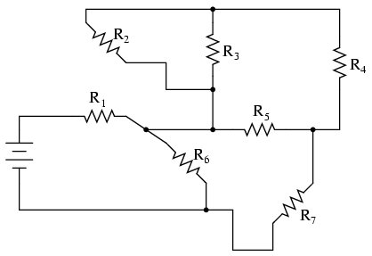
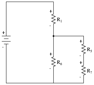
Let’s start with the following (convoluted) circuit diagram. Perhaps this diagram was originally drawn this way by a technician or engineer. Perhaps it was sketched as someone traced the wires and connections of a real circuit. In any case, here it is in all its ugliness:
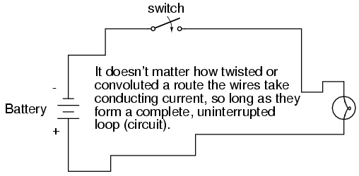
With electric circuits and circuit diagrams, the length and routing of wire connecting components in a circuit matters little. (Actually, in some AC circuits it becomes critical, and very long wire lengths can contribute unwanted resistance to both AC and DC circuits, but in most cases wire length is irrelevant.) What this means for us is that we can lengthen, shrink, and/or bend connecting wires without affecting the operation of our circuit.
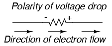
The strategy I have found easiest to apply is to start by tracing the current from one terminal of the battery around to the other terminal, following the loop of components closest to the battery and ignoring all other wires and components for the time being. While tracing the path of the loop, mark each resistor with the appropriate polarity for voltage drop.
In this case, I’ll begin my tracing of this circuit at the negative terminal of the battery and finish at the positive terminal, in the same general direction as the electrons would flow. When tracing this direction, I will mark each resistor with the polarity of negative on the entering side and positive on the exiting side, for that is how the actual polarity will be as electrons (negative in charge) enter and exit a resistor:
Any components encountered along this short loop are drawn vertically in order:
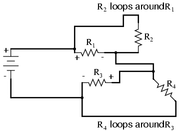
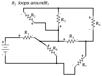
Now, proceed to trace any loops of components connected around components that were just traced. In this case, there’s a loop around R1 formed by R2, and another loop around R3 formed by R4:
Tracing those loops, I draw R2 and R4 in parallel with R1 and R3 (respectively) on the vertical diagram. Noting the polarity of voltage drops across R3 and R1, I mark R4 and R2 likewise:
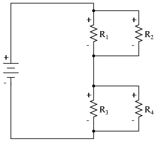
Now we have a circuit that is very easily understood and analyzed. In this case, it is identical to the four-resistor series-parallel configuration we examined earlier in the chapter.
Let’s look at another example, even uglier than the one before:
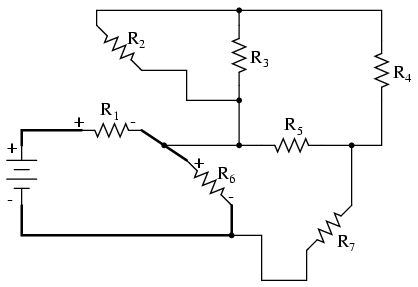
The first loop I’ll trace is from the negative (-) side of the battery, through R6, through R1, and back to the positive (+) end of the battery:
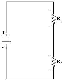
Re-drawing vertically and keeping track of voltage drop polarities along the way, our equivalent circuit starts out looking like this:
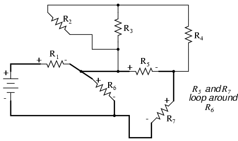
Next, we can proceed to follow the next loop around one of the traced resistors (R6), in this case, the loop formed by R5 and R7. As before, we start at the negative end of R6 and proceed to the positive end of R6, marking voltage drop polarities across R7 and R5 as we go:
Now we add the R5–R7 loop to the vertical drawing. Notice how the voltage drop polarities across R7 and R5 correspond with that of R6, and how this is the same as what we found tracing R7 and R5 in the original circuit:
We repeat the process again, identifying and tracing another loop around an already-traced resistor. In this case, the R3–R4 loop around R5 looks like a good loop to trace next:
Adding the R3–R4 loop to the vertical drawing, marking the correct polarities as well:
With only one remaining resistor left to trace, then next step is obvious: trace the loop formed by R2 around R3:
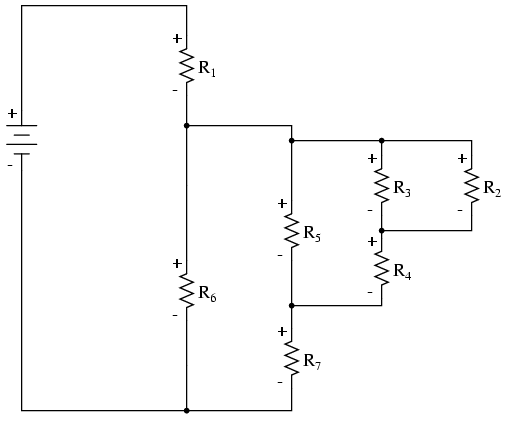
Adding R2 to the vertical drawing, and we’re finished! The result is a diagram that’s very easy to understand compared to the original:
This simplified layout greatly eases the task of determining where to start and how to proceed in reducing the circuit down to a single equivalent (total) resistance. Notice how the circuit has been re-drawn, all we have to do is start from the right-hand side and work our way left, reducing simple-series and simple-parallel resistor combinations one group at a time until we’re done.
In this particular case, we would start with the simple parallel combination of R2 and R3, reducing it to a single resistance. Then, we would take that equivalent resistance (R2//R3) and the one in series with it (R4), reducing them to another equivalent resistance (R2//R3–R4). Next, we would proceed to calculate the parallel equivalent of that resistance (R2//R3–R4) with R5, then in series with R7, then in parallel with R6, then in series with R1 to give us a grand total resistance for the circuit as a whole.
From there we could calculate total current from total voltage and total resistance (I=E/R), then “expand” the circuit back into its original form one stage at a time, distributing the appropriate values of voltage and current to the resistances as we go.
REVIEW:
Wires in diagrams and in real circuits can be lengthened, shortened, and/or moved without affecting circuit operation.
To simplify a convoluted circuit schematic, follow these steps:
Trace current from one side of the battery to the other, following any single path (“loop”) to the battery. Sometimes it works better to start with the loop containing the most components, but regardless of the path taken the result will be accurate. Mark polarity of voltage drops across each resistor as you trace the loop. Draw those components you encounter along this loop in a vertical schematic.
Mark traced components in the original diagram and trace remaining loops of components in the circuit. Use polarity marks across traced components as guides for what connects where. Document new components in loops on the vertical re-draw schematic as well.
Repeat last step as often as needed until all components in original diagram have been traced.
Component Failure Analysis
“I consider that I understand an equation when I can predict the properties of its solutions, without actually solving it.”
P.A.M Dirac, physicist
There is a lot of truth to that quote from Dirac. With a little modification, I can extend his wisdom to electric circuits by saying, “I consider that I understand a circuit when I can predict the approximate effects of various changes made to it without actually performing any calculations.”
At the end of the series and parallel circuits chapter, we briefly considered how circuits could be analyzed in a qualitative rather than quantitative manner. Building this skill is an important step towards becoming a proficient troubleshooter of electric circuits. Once you have a thorough understanding of how any particular failure will affect a circuit (i.e. you don’t have to perform any arithmetic to predict the results), it will be much easier to work the other way around: pinpointing the source of trouble by assessing how a circuit is behaving.
Also shown at the end of the series and parallel circuits chapter was how the table method works just as well for aiding failure analysis as it does for the analysis of healthy circuits. We may take this technique one step further and adapt it for total qualitative analysis. By “qualitative” I mean working with symbols representing “increase,” “decrease,” and “same” instead of precise numerical figures. We can still use the principles of series and parallel circuits, and the concepts of Ohm’s Law, we’ll just use symbolic qualities instead of numerical quantities. By doing this, we can gain more of an intuitive “feel” for how circuits work rather than leaning on abstract equations, attaining Dirac’s definition of “understanding.”
Enough talk. Let’s try this technique on a real circuit example and see how it works:
This is the first “convoluted” circuit we straightened out for analysis in the last section. Since you already know how this particular circuit reduces to series and parallel sections, I’ll skip the process and go straight to the final form:
R3 and R4 are in parallel with each other; so are R1 and R2. The parallel equivalents of R3//R4 and R1//R2 are in series with each other. Expressed in symbolic form, the total resistance for this circuit is as follows:
RTotal = (R1//R2)–(R3//R4)
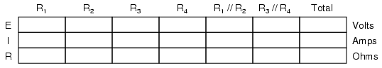
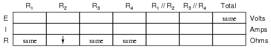
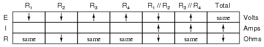
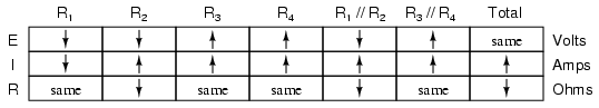
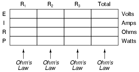
First, we need to formulate a table with all the necessary rows and columns for this circuit:
Next, we need a failure scenario. Let’s suppose that resistor R2 were to fail shorted. We will assume that all other components maintain their original values. Because we’ll be analyzing this circuit qualitatively rather than quantitatively, we won’t be inserting any real numbers into the table. For any quantity unchanged after the component failure, we’ll use the word “same” to represent “no change from before.” For any quantity that has changed as a result of the failure, we’ll use a down arrow for “decrease” and an up arrow for “increase.” As usual, we start by filling in the spaces of the table for individual resistances and total voltage, our “given” values:
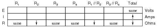
The only “given” value different from the normal state of the circuit is R2, which we said was failed shorted (abnormally low resistance). All other initial values are the same as they were before, as represented by the “same” entries. All we have to do now is work through the familiar Ohm’s Law and series-parallel principles to determine what will happen to all the other circuit values.
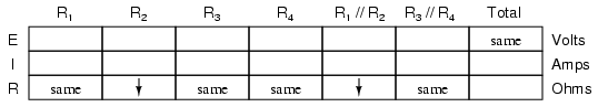
First, we need to determine what happens to the resistances of parallel subsections R1//R2 and R3//R4. If neither R3 nor R4 have changed in resistance value, then neither will their parallel combination. However, since the resistance of R2 has decreased while R1 has stayed the same, their parallel combination must decrease in resistance as well:
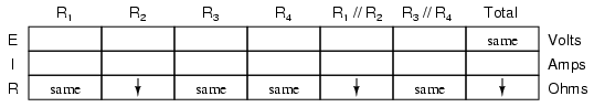
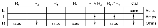
Now, we need to figure out what happens to the total resistance. This part is easy: when we’re dealing with only one component change in the circuit, the change in total resistance will be in the same direction as the change of the failed component. This is not to say that the magnitude of change between individual component and total circuit will be the same, merely the direction of change. In other words, if any single resistor decreases in value, then the total circuit resistance must also decrease, and vice versa. In this case, since R2 is the only failed component, and its resistance has decreased, the total resistance must decrease:
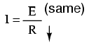
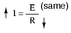
Now we can apply Ohm’s Law (qualitatively) to the Total column in the table. Given the fact that total voltage has remained the same and total resistance has decreased, we can conclude that total current must increase (I=E/R).
In case you’re not familiar with the qualitative assessment of an equation, it works like this. First, we write the equation as solved for the unknown quantity. In this case, we’re trying to solve for current, given voltage and resistance:
Now that our equation is in the proper form, we assess what change (if any) will be experienced by “I,” given the change(s) to “E” and “R”:
If the denominator of a fraction decreases in value while the numerator stays the same, then the overall value of the fraction must increase:
Therefore, Ohm’s Law (I=E/R) tells us that the current (I) will increase. We’ll mark this conclusion in our table with an “up” arrow:
With all resistance places filled in the table and all quantities determined in the Total column, we can proceed to determine the other voltages and currents. Knowing that the total resistance in this table was the result of R1//R2 and R3//R4 in series, we know that the value of total current will be the same as that in R1//R2 and R3//R4 (because series components share the same current). Therefore, if total current increased, then current through R1//R2 and R3//R4 must also have increased with the failure of R2:
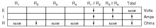
Fundamentally, what we’re doing here with a qualitative usage of Ohm’s Law and the rules of series and parallel circuits is no different from what we’ve done before with numerical figures. In fact, its a lot easier because you don’t have to worry about making an arithmetic or calculator keystroke error in a calculation. Instead, you’re just focusing on the principles behind the equations. From our table above, we can see that Ohm’s Law should be applicable to the R1//R2 and R3//R4 columns. For R3//R4, we figure what happens to the voltage, given an increase in current and no change in resistance. Intuitively, we can see that this must result in an increase in voltage across the parallel combination of R3//R4:
But how do we apply the same Ohm’s Law formula (E=IR) to the R1//R2 column, where we have resistance decreasing and current increasing? It’s easy to determine if only one variable is changing, as it was with R3//R4, but with two variables moving around and no definite numbers to work with, Ohm’s Law isn’t going to be much help. However, there is another rule we can apply horizontally to determine what happens to the voltage across R1//R2: the rule for voltage in series circuits. If the voltages across R1//R2 and R3//R4 add up to equal the total (battery) voltage and we know that the R3//R4 voltage has increased while total voltage has stayed the same, then the voltage across R1//R2must have decreased with the change of R2‘s resistance value:
Now we’re ready to proceed to some new columns in the table. Knowing that R3 and R4 comprise the parallel subsection R3//R4, and knowing that voltage is shared equally between parallel components, the increase in voltage seen across the parallel combination R3//R4 must also be seen across R3 and R4 individually:
The same goes for R1 and R2. The voltage decrease seen across the parallel combination of R1 and R2 will be seen across R1 and R2 individually:
Applying Ohm’s Law vertically to those columns with unchanged (“same”) resistance values, we can tell what the current will do through those components. Increased voltage across an unchanged resistance leads to increased current. Conversely, decreased voltage across an unchanged resistance leads to decreased current:
Once again we find ourselves in a position where Ohm’s Law can’t help us: for R2, both voltage and resistance have decreased, but without knowing how much each one has changed, we can’t use the I=E/R formula to qualitatively determine the resulting change in current. However, we can still apply the rules of series and parallel circuits horizontally. We know that the current through the R1//R2 parallel combination has increased, and we also know that the current through R1 has decreased. One of the rules of parallel circuits is that total current is equal to the sum of the individual branch currents. In this case, the current through R1//R2 is equal to the current through R1 added to the current through R2. If current through R1//R2 has increased while current through R1 has decreased, current through R2must have increased:
And with that, our table of qualitative values stands completed. This particular exercise may look laborious due to all the detailed commentary, but the actual process can be performed very quickly with some practice. An important thing to realize here is that the general procedure is little different from quantitative analysis: start with the known values, then proceed to determining total resistance, then total current, then transfer figures of voltage and current as allowed by the rules of series and parallel circuits to the appropriate columns.
A few general rules can be memorized to assist and/or to check your progress when proceeding with such an analysis:
For any single component failure (open or shorted), the total resistance will always change in the same direction (either increase or decrease) as the resistance change of the failed component.
When a component fails shorted, its resistance always decreases. Also, the current through it will increase, and the voltage across it may drop. I say “may” because in some cases it will remain the same (case in point: a simple parallel circuit with an ideal power source).
When a component fails open, its resistance always increases. The current through that component will decrease to zero, because it is an incomplete electrical path (no continuity). This may result in an increase of voltage across it. The same exception stated above applies here as well: in a simple parallel circuit with an ideal voltage source, the voltage across an open-failed component will remain unchanged.
Building Series-Parallel Resistor Circuits
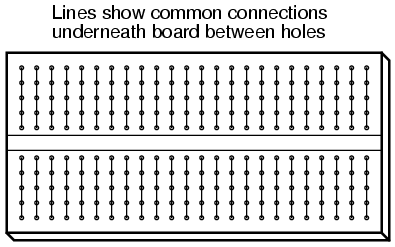
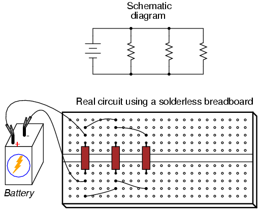
Once again, when building battery/resistor circuits, the student or hobbyist is faced with several different modes of construction. Perhaps the most popular is the solderless breadboard: a platform for constructing temporary circuits by plugging components and wires into a grid of interconnected points. A breadboard appears to be nothing but a plastic frame with hundreds of small holes in it. Underneath each hole, though, is a spring clip which connects to other spring clips beneath other holes. The connection pattern between holes is simple and uniform:
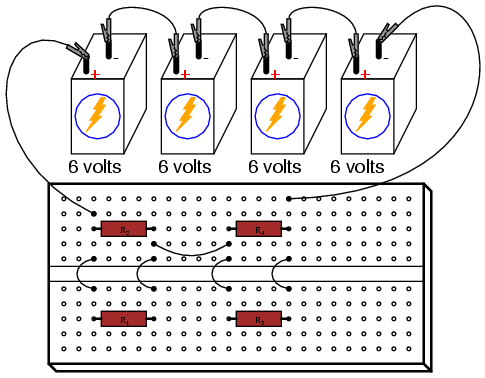
Suppose we wanted to construct the following series-parallel combination circuit on a breadboard:
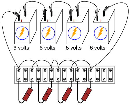
The recommended way to do so on a breadboard would be to arrange the resistors in approximately the same pattern as seen in the schematic, for ease of relation to the schematic. If 24 volts is required and we only have 6-volt batteries available, four may be connected in series to achieve the same effect:
This is by no means the only way to connect these four resistors together to form the circuit shown in the schematic. Consider this alternative layout:
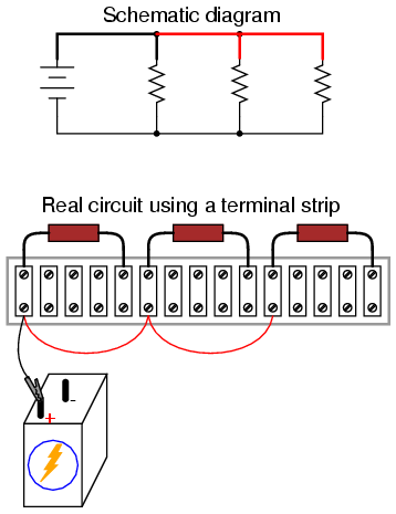
If greater permanence is desired without resorting to soldering or wire-wrapping, one could choose to construct this circuit on a terminal strip (also called a barrier strip, or terminal block). In this method, components and wires are secured by mechanical tension underneath screws or heavy clips attached to small metal bars. The metal bars, in turn, are mounted on a nonconducting body to keep them electrically isolated from each other.
Building a circuit with components secured to a terminal strip isn’t as easy as plugging components into a breadboard, principally because the components cannot be physically arranged to resemble the schematic layout. Instead, the builder must understand how to “bend” the schematic’s representation into the real-world layout of the strip. Consider one example of how the same four-resistor circuit could be built on a terminal strip:
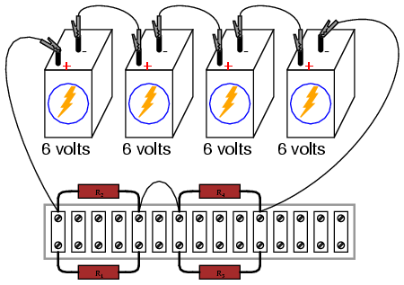
Another terminal strip layout, simpler to understand and relate to the schematic, involves anchoring parallel resistors (R1//R2 and R3//R4) to the same two terminal points on the strip like this:
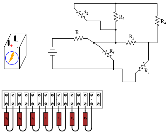
Building more complex circuits on a terminal strip involves the same spatial-reasoning skills, but of course requires greater care and planning. Take for instance this complex circuit, represented in schematic form:
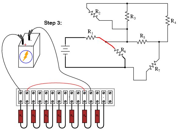
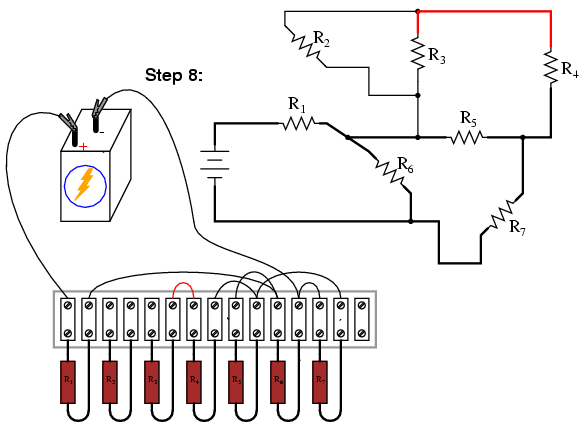
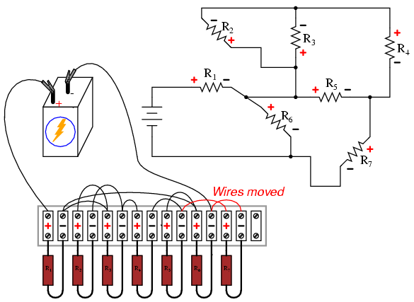
The terminal strip used in the prior example barely has enough terminals to mount all seven resistors required for this circuit! It will be a challenge to determine all the necessary wire connections between resistors, but with patience it can be done. First, begin by installing and labeling all resistors on the strip. The original schematic diagram will be shown next to the terminal strip circuit for reference:
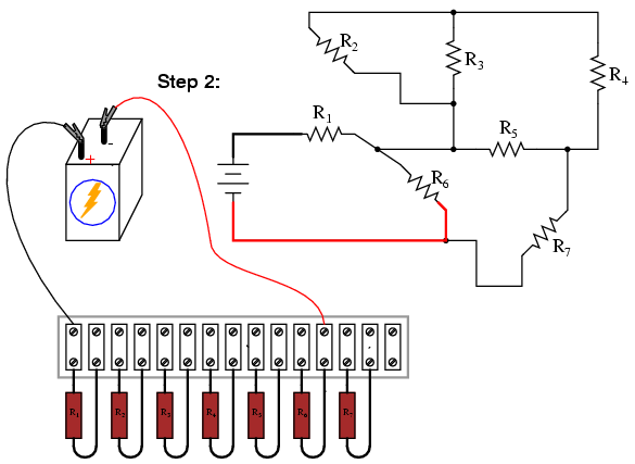
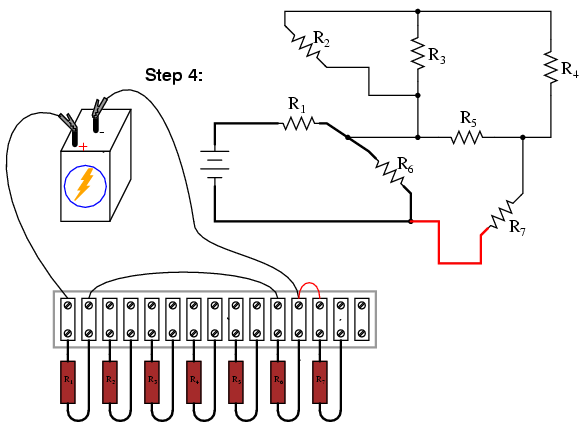
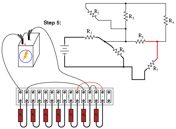
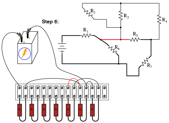
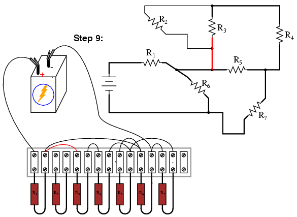
Next, begin connecting components together wire by wire as shown in the schematic. Over-draw connecting lines in the schematic to indicate completion in the real circuit. Watch this sequence of illustrations as each individual wire is identified in the schematic, then added to the real circuit:
Although there are minor variations possible with this terminal strip circuit, the choice of connections shown in this example sequence is both electrically accurate (electrically identical to the schematic diagram) and carries the additional benefit of not burdening any one screw terminal on the strip with more than two wire ends, a good practice in any terminal strip circuit.
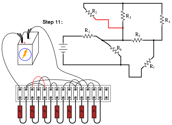
An example of a “variant” wire connection might be the very last wire added (step 11), which I placed between the left terminal of R2 and the left terminal of R3. This last wire completed the parallel connection between R2 and R3 in the circuit. However, I could have placed this wire instead between the left terminal of R2 and the right terminal of R1, since the right terminal of R1 is already connected to the left terminal of R3 (having been placed there in step 9) and so is electrically common with that one point. Doing this, though, would have resulted in three wires secured to the right terminal of R1 instead of two, which is a faux pax in terminal strip etiquette. Would the circuit have worked this way? Certainly! It’s just that more than two wires secured at a single terminal makes for a “messy” connection: one that is aesthetically unpleasing and may place undue stress on the screw terminal.
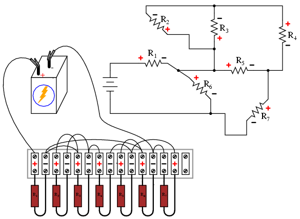
Another variation would be to reverse the terminal connections for resistor R7. As shown in the last diagram, the voltage polarity across R7 is negative on the left and positive on the right (- , +), whereas all the other resistor polarities are positive on the left and negative on the right (+ , -):
While this poses no electrical problem, it might cause confusion for anyone measuring resistor voltage drops with a voltmeter, especially an analog voltmeter which will “peg” downscale when subjected to a voltage of the wrong polarity. For the sake of consistency, it might be wise to arrange all wire connections so that all resistor voltage drop polarities are the same, like this:
Though electrons do not care about such consistency in component layout, people do. This illustrates an important aspect of any engineering endeavor: the human factor. Whenever a design may be modified for easier comprehension and/or easier maintenance — with no sacrifice of functional performance — it should be done so.
REVIEW:
Circuits built on terminal strips can be difficult to lay out, but when built they are robust enough to be considered permanent, yet easy to modify.
It is bad practice to secure more than two wire ends and/or component leads under a single terminal screw or clip on a terminal strip. Try to arrange connecting wires so as to avoid this condition.
Whenever possible, build your circuits with clarity and ease of understanding in mind. Even though component and wiring layout is usually of little consequence in DC circuit function, it matters significantly for the sake of the person who has to modify or troubleshoot it later.
Contributors
Contributors to this chapter are listed in chronological order of their contributions, from most recent to first. See Appendix 2 (Contributor List) for dates and contact information.
Tony Armstrong (January 23, 2003): Suggested reversing polarity on resistor R7 in last terminal strip circuit.
Jason Starck (June 2000): HTML document formatting, which led to a much better-looking second edition.
Ron LaPlante (October 1998): helped create “table” method of series and parallel circuit analysis.
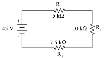
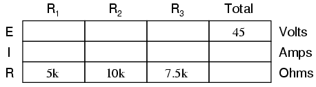
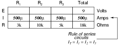
Let’s analyze a simple series circuit, determining the voltage drops across individual resistors:
From the given values of individual resistances, we can determine a total circuit resistance, knowing that resistances add in series:
From here, we can use Ohm’s Law (I=E/R) to determine the total current, which we know will be the same as each resistor current, currents being equal in all parts of a series circuit:
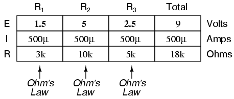
Now, knowing that the circuit current is 2 mA, we can use Ohm’s Law (E=IR) to calculate voltage across each resistor:
It should be apparent that the voltage drop across each resistor is proportional to its resistance, given that the current is the same through all resistors. Notice how the voltage across R2 is double that of the voltage across R1, just as the resistance of R2 is double that of R1.
If we were to change the total voltage, we would find this proportionality of voltage drops remains constant:
The voltage across R2 is still exactly twice that of R1‘s drop, despite the fact that the source voltage has changed. The proportionality of voltage drops (ratio of one to another) is strictly a function of resistance values.
With a little more observation, it becomes apparent that the voltage drop across each resistor is also a fixed proportion of the supply voltage. The voltage across R1, for example, was 10 volts when the battery supply was 45 volts. When the battery voltage was increased to 180 volts (4 times as much), the voltage drop across R1 also increased by a factor of 4 (from 10 to 40 volts). The ratio between R1‘s voltage drop and total voltage, however, did not change:
Likewise, none of the other voltage drop ratios changed with the increased supply voltage either:
For this reason a series circuit is often called a voltage divider for its ability to proportion — or divide — the total voltage into fractional portions of constant ratio. With a little bit of algebra, we can derive a formula for determining series resistor voltage drop given nothing more than total voltage, individual resistance, and total resistance:
The ratio of individual resistance to total resistance is the same as the ratio of individual voltage drop to total supply voltage in a voltage divider circuit. This is known as the voltage divider formula, and it is a short-cut method for determining voltage drop in a series circuit without going through the current calculation(s) of Ohm’s Law.
Using this formula, we can re-analyze the example circuit’s voltage drops in fewer steps:
Voltage dividers find wide application in electric meter circuits, where specific combinations of series resistors are used to “divide” a voltage into precise proportions as part of a voltage measurement device.
One device frequently used as a voltage-dividing component is the potentiometer, which is a resistor with a movable element positioned by a manual knob or lever. The movable element, typically called a wiper, makes contact with a resistive strip of material (commonly called the slidewire if made of resistive metal wire) at any point selected by the manual control:
The wiper contact is the left-facing arrow symbol drawn in the middle of the vertical resistor element. As it is moved up, it contacts the resistive strip closer to terminal 1 and further away from terminal 2, lowering resistance to terminal 1 and raising resistance to terminal 2. As it is moved down, the opposite effect results. The resistance as measured between terminals 1 and 2 is constant for any wiper position.
Shown here are internal illustrations of two potentiometer types, rotary and linear:
Some linear potentiometers are actuated by straight-line motion of a lever or slide button. Others, like the one depicted in the previous illustration, are actuated by a turn-screw for fine adjustment ability. The latter units are sometimes referred to as trimpots, because they work well for applications requiring a variable resistance to be “trimmed” to some precise value. It should be noted that not all linear potentiometers have the same terminal assignments as shown in this illustration. With some, the wiper terminal is in the middle, between the two end terminals.
The following photograph shows a real, rotary potentiometer with exposed wiper and slidewire for easy viewing. The shaft which moves the wiper has been turned almost fully clockwise so that the wiper is nearly touching the left terminal end of the slidewire:
Here is the same potentiometer with the wiper shaft moved almost to the full-counterclockwise position, so that the wiper is near the other extreme end of travel:
If a constant voltage is applied between the outer terminals (across the length of the slidewire), the wiper position will tap off a fraction of the applied voltage, measurable between the wiper contact and either of the other two terminals. The fractional value depends entirely on the physical position of the wiper:
Just like the fixed voltage divider, the potentiometer’s voltage division ratio is strictly a function of resistance and not of the magnitude of applied voltage. In other words, if the potentiometer knob or lever is moved to the 50 percent (exact center) position, the voltage dropped between wiper and either outside terminal would be exactly 1/2 of the applied voltage, no matter what that voltage happens to be, or what the end-to-end resistance of the potentiometer is. In other words, a potentiometer functions as a variable voltage divider where the voltage division ratio is set by wiper position.
This application of the potentiometer is a very useful means of obtaining a variable voltage from a fixed-voltage source such as a battery. If a circuit you’re building requires a certain amount of voltage that is less than the value of an available battery’s voltage, you may connect the outer terminals of a potentiometer across that battery and “dial up” whatever voltage you need between the potentiometer wiper and one of the outer terminals for use in your circuit:
When used in this manner, the name potentiometer makes perfect sense: they meter (control) the potential (voltage) applied across them by creating a variable voltage-divider ratio. This use of the three-terminal potentiometer as a variable voltage divider is very popular in circuit design.
Shown here are several small potentiometers of the kind commonly used in consumer electronic equipment and by hobbyists and students in constructing circuits:
The smaller units on the very left and very right are designed to plug into a solderless breadboard or be soldered into a printed circuit board. The middle units are designed to be mounted on a flat panel with wires soldered to each of the three terminals.
Here are three more potentiometers, more specialized than the set just shown:
The large “Helipot” unit is a laboratory potentiometer designed for quick and easy connection to a circuit. The unit in the lower-left corner of the photograph is the same type of potentiometer, just without a case or 10-turn counting dial. Both of these potentiometers are precision units, using multi-turn helical-track resistance strips and wiper mechanisms for making small adjustments. The unit on the lower-right is a panel-mount potentiometer, designed for rough service in industrial applications.
REVIEW:
Series circuits proportion, or divide, the total supply voltage among individual voltage drops, the proportions being strictly dependent upon resistances: ERn = ETotal (Rn / RTotal)
A potentiometer is a variable-resistance component with three connection points, frequently used as an adjustable voltage divider.
Kirchoff’s Voltage Law
Let’s take another look at our example series circuit, this time numbering the points in the circuit for voltage reference:
If we were to connect a voltmeter between points 2 and 1, red test lead to point 2 and black test lead to point 1, the meter would register +45 volts. Typically the “+” sign is not shown, but rather implied, for positive readings in digital meter displays. However, for this lesson the polarity of the voltage reading is very important and so I will show positive numbers explicitly:
When a voltage is specified with a double subscript (the characters “2-1” in the notation “E2-1“), it means the voltage at the first point (2) as measured in reference to the second point (1). A voltage specified as “Ecd” would mean the voltage as indicated by a digital meter with the red test lead on point “c” and the black test lead on point “d”: the voltage at “c” in reference to “d”.
If we were to take that same voltmeter and measure the voltage drop across each resistor, stepping around the circuit in a clockwise direction with the red test lead of our meter on the point ahead and the black test lead on the point behind, we would obtain the following readings:
We should already be familiar with the general principle for series circuits stating that individual voltage drops add up to the total applied voltage, but measuring voltage drops in this manner and paying attention to the polarity (mathematical sign) of the readings reveals another facet of this principle: that the voltages measured as such all add up to zero:
This principle is known as Kirchhoff’s Voltage Law (discovered in 1847 by Gustav R. Kirchhoff, a German physicist), and it can be stated as such:
“The algebraic sum of all voltages in a loop must equal zero”
By algebraic, I mean accounting for signs (polarities) as well as magnitudes. By loop, I mean any path traced from one point in a circuit around to other points in that circuit, and finally back to the initial point. In the above example the loop was formed by following points in this order: 1-2-3-4-1. It doesn’t matter which point we start at or which direction we proceed in tracing the loop; the voltage sum will still equal zero. To demonstrate, we can tally up the voltages in loop 3-2-1-4-3 of the same circuit:
This may make more sense if we re-draw our example series circuit so that all components are represented in a straight line:
It’s still the same series circuit, just with the components arranged in a different form. Notice the polarities of the resistor voltage drops with respect to the battery: the battery’s voltage is negative on the left and positive on the right, whereas all the resistor voltage drops are oriented the other way: positive on the left and negative on the right. This is because the resistors are resisting the flow of electrons being pushed by the battery. In other words, the “push” exerted by the resistors against the flow of electrons must be in a direction opposite the source of electromotive force.
Here we see what a digital voltmeter would indicate across each component in this circuit, black lead on the left and red lead on the right, as laid out in horizontal fashion:
If we were to take that same voltmeter and read voltage across combinations of components, starting with only R1 on the left and progressing across the whole string of components, we will see how the voltages add algebraically (to zero):
The fact that series voltages add up should be no mystery, but we notice that the polarity of these voltages makes a lot of difference in how the figures add. While reading voltage across R1, R1–R2, and R1–R2–R3 (I’m using a “double-dash” symbol “–” to represent the series connection between resistors R1, R2, and R3), we see how the voltages measure successively larger (albeit negative) magnitudes, because the polarities of the individual voltage drops are in the same orientation (positive left, negative right). The sum of the voltage drops across R1, R2, and R3 equals 45 volts, which is the same as the battery’s output, except that the battery’s polarity is opposite that of the resistor voltage drops (negative left, positive right), so we end up with 0 volts measured across the whole string of components.
That we should end up with exactly 0 volts across the whole string should be no mystery, either. Looking at the circuit, we can see that the far left of the string (left side of R1: point number 2) is directly connected to the far right of the string (right side of battery: point number 2), as necessary to complete the circuit. Since these two points are directly connected, they are electrically common to each other. And, as such, the voltage between those two electrically common points must be zero.
Kirchhoff’s Voltage Law (sometimes denoted as KVL for short) will work for any circuit configuration at all, not just simple series. Note how it works for this parallel circuit:
Being a parallel circuit, the voltage across every resistor is the same as the supply voltage: 6 volts. Tallying up voltages around loop 2-3-4-5-6-7-2, we get:
Note how I label the final (sum) voltage as E2-2. Since we began our loop-stepping sequence at point 2 and ended at point 2, the algebraic sum of those voltages will be the same as the voltage measured between the same point (E2-2), which of course must be zero.
The fact that this circuit is parallel instead of series has nothing to do with the validity of Kirchhoff’s Voltage Law. For that matter, the circuit could be a “black box” — its component configuration completely hidden from our view, with only a set of exposed terminals for us to measure voltage between — and KVL would still hold true:
Try any order of steps from any terminal in the above diagram, stepping around back to the original terminal, and you’ll find that the algebraic sum of the voltages always equals zero.
Furthermore, the “loop” we trace for KVL doesn’t even have to be a real current path in the closed-circuit sense of the word. All we have to do to comply with KVL is to begin and end at the same point in the circuit, tallying voltage drops and polarities as we go between the next and the last point. Consider this absurd example, tracing “loop” 2-3-6-3-2 in the same parallel resistor circuit:
KVL can be used to determine an unknown voltage in a complex circuit, where all other voltages around a particular “loop” are known. Take the following complex circuit (actually two series circuits joined by a single wire at the bottom) as an example:
To make the problem simpler, I’ve omitted resistance values and simply given voltage drops across each resistor. The two series circuits share a common wire between them (wire 7-8-9-10), making voltage measurements between the two circuits possible. If we wanted to determine the voltage between points 4 and 3, we could set up a KVL equation with the voltage between those points as the unknown:
Stepping around the loop 3-4-9-8-3, we write the voltage drop figures as a digital voltmeter would register them, measuring with the red test lead on the point ahead and black test lead on the point behind as we progress around the loop. Therefore, the voltage from point 9 to point 4 is a positive (+) 12 volts because the “red lead” is on point 9 and the “black lead” is on point 4. The voltage from point 3 to point 8 is a positive (+) 20 volts because the “red lead” is on point 3 and the “black lead” is on point 8. The voltage from point 8 to point 9 is zero, of course, because those two points are electrically common.
Our final answer for the voltage from point 4 to point 3 is a negative (-) 32 volts, telling us that point 3 is actually positive with respect to point 4, precisely what a digital voltmeter would indicate with the red lead on point 4 and the black lead on point 3:
In other words, the initial placement of our “meter leads” in this KVL problem was “backwards.” Had we generated our KVL equation starting with E3-4 instead of E4-3, stepping around the same loop with the opposite meter lead orientation, the final answer would have been E3-4 = +32 volts:
It is important to realize that neither approach is “wrong.” In both cases, we arrive at the correct assessment of voltage between the two points, 3 and 4: point 3 is positive with respect to point 4, and the voltage between them is 32 volts.
REVIEW:
Kirchhoff’s Voltage Law (KVL): “The algebraic sum of all voltages in a loop must equal zero”
Current Divider Circuits
Let’s analyze a simple parallel circuit, determining the branch currents through individual resistors:
Knowing that voltages across all components in a parallel circuit are the same, we can fill in our voltage/current/resistance table with 6 volts across the top row:
Using Ohm’s Law (I=E/R) we can calculate each branch current:
Knowing that branch currents add up in parallel circuits to equal the total current, we can arrive at total current by summing 6 mA, 2 mA, and 3 mA:
The final step, of course, is to figure total resistance. This can be done with Ohm’s Law (R=E/I) in the “total” column, or with the parallel resistance formula from individual resistances. Either way, we’ll get the same answer:
Once again, it should be apparent that the current through each resistor is related to its resistance, given that the voltage across all resistors is the same. Rather than being directly proportional, the relationship here is one of inverse proportion. For example, the current through R1 is twice as much as the current through R3, which has twice the resistance of R1.
If we were to change the supply voltage of this circuit, we find that (surprise!) these proportional ratios do not change:
The current through R1 is still exactly twice that of R3, despite the fact that the source voltage has changed. The proportionality between different branch currents is strictly a function of resistance.
Also reminiscent of voltage dividers is the fact that branch currents are fixed proportions of the total current. Despite the fourfold increase in supply voltage, the ratio between any branch current and the total current remains unchanged:
For this reason a parallel circuit is often called a current divider for its ability to proportion — or divide — the total current into fractional parts. With a little bit of algebra, we can derive a formula for determining parallel resistor current given nothing more than total current, individual resistance, and total resistance:
The ratio of total resistance to individual resistance is the same ratio as individual (branch) current to total current. This is known as the current divider formula, and it is a short-cut method for determining branch currents in a parallel circuit when the total current is known.
Using the original parallel circuit as an example, we can re-calculate the branch currents using this formula, if we start by knowing the total current and total resistance:
If you take the time to compare the two divider formulae, you’ll see that they are remarkably similar. Notice, however, that the ratio in the voltage divider formula is Rn (individual resistance) divided by RTotal, and how the ratio in the current divider formula is RTotal divided by Rn:
It is quite easy to confuse these two equations, getting the resistance ratios backwards. One way to help remember the proper form is to keep in mind that both ratios in the voltage and current divider equations must equal less than one. After all these are divider equations, not multiplier equations! If the fraction is upside-down, it will provide a ratio greater than one, which is incorrect. Knowing that total resistance in a series (voltage divider) circuit is always greater than any of the individual resistances, we know that the fraction for that formula must be Rn over RTotal. Conversely, knowing that total resistance in a parallel (current divider) circuit is always less then any of the individual resistances, we know that the fraction for that formula must be RTotal over Rn.
Current divider circuits also find application in electric meter circuits, where a fraction of a measured current is desired to be routed through a sensitive detection device. Using the current divider formula, the proper shunt resistor can be sized to proportion just the right amount of current for the device in any given instance:
REVIEW:
Parallel circuits proportion, or “divide,” the total circuit current among individual branch currents, the proportions being strictly dependent upon resistances: In = ITotal (RTotal / Rn)
Kirchoff’s Current Law
Let’s take a closer look at that last parallel example circuit:
Solving for all values of voltage and current in this circuit:
At this point, we know the value of each branch current and of the total current in the circuit. We know that the total current in a parallel circuit must equal the sum of the branch currents, but there’s more going on in this circuit than just that. Taking a look at the currents at each wire junction point (node) in the circuit, we should be able to see something else:
At each node on the negative “rail” (wire 8-7-6-5) we have current splitting off the main flow to each successive branch resistor. At each node on the positive “rail” (wire 1-2-3-4) we have current merging together to form the main flow from each successive branch resistor. This fact should be fairly obvious if you think of the water pipe circuit analogy with every branch node acting as a “tee” fitting, the water flow splitting or merging with the main piping as it travels from the output of the water pump toward the return reservoir or sump.
If we were to take a closer look at one particular “tee” node, such as node 3, we see that the current entering the node is equal in magnitude to the current exiting the node:
From the right and from the bottom, we have two currents entering the wire connection labeled as node 3. To the left, we have a single current exiting the node equal in magnitude to the sum of the two currents entering. To refer to the plumbing analogy: so long as there are no leaks in the piping, what flow enters the fitting must also exit the fitting. This holds true for any node (“fitting”), no matter how many flows are entering or exiting. Mathematically, we can express this general relationship as such:
Mr. Kirchhoff decided to express it in a slightly different form (though mathematically equivalent), calling it Kirchhoff’s Current Law (KCL):
Summarized in a phrase, Kirchhoff’s Current Law reads as such:
“The algebraic sum of all currents entering and exiting a node must equal zero”
That is, if we assign a mathematical sign (polarity) to each current, denoting whether they enter (+) or exit (-) a node, we can add them together to arrive at a total of zero, guaranteed.
Taking our example node (number 3), we can determine the magnitude of the current exiting from the left by setting up a KCL equation with that current as the unknown value:
The negative (-) sign on the value of 5 milliamps tells us that the current is exiting the node, as opposed to the 2 milliamp and 3 milliamp currents, which must both be positive (and therefore entering the node). Whether negative or positive denotes current entering or exiting is entirely arbitrary, so long as they are opposite signs for opposite directions and we stay consistent in our notation, KCL will work.
Together, Kirchhoff’s Voltage and Current Laws are a formidable pair of tools useful in analyzing electric circuits. Their usefulness will become all the more apparent in a later chapter (“Network Analysis”), but suffice it to say that these Laws deserve to be memorized by the electronics student every bit as much as Ohm’s Law.
REVIEW:
Kirchhoff’s Current Law (KCL): “The algebraic sum of all currents entering and exiting a node must equal zero”
Contributors
Contributors to this chapter are listed in chronological order of their contributions, from most recent to first. See Appendix 2 (Contributor List) for dates and contact information.
Jason Starck (June 2000): HTML document formatting, which led to a much better-looking second edition.
Ron LaPlante (October 1998): helped create “table” method of series and parallel circuit analysis.
In many disciplines of science and engineering, very large and very small numerical quantities must be managed. Some of these quantities are mind-boggling in their size, either extremely small or extremely large. Take for example the mass of a proton, one of the constituent particles of an atom’s nucleus:
Proton mass = 0.00000000000000000000000167 grams
Or, consider the number of electrons passing by a point in a circuit every second with a steady electric current of 1 amp:
1 amp = 6,250,000,000,000,000,000 electrons per second
A lot of zeros, isn’t it? Obviously, it can get quite confusing to have to handle so many zero digits in numbers such as this, even with the help of calculators and computers.
Take note of those two numbers and of the relative sparsity of non-zero digits in them. For the mass of the proton, all we have is a “167” preceded by 23 zeros before the decimal point. For the number of electrons per second in 1 amp, we have “625” followed by 16 zeros. We call the span of non-zero digits (from first to last), plus any zero digits not merely used for placeholding, the “significant digits” of any number.
The significant digits in a real-world measurement are typically reflective of the accuracy of that measurement. For example, if we were to say that a car weighs 3,000 pounds, we probably don’t mean that the car in question weighs exactly 3,000 pounds, but that we’ve rounded its weight to a value more convenient to say and remember. That rounded figure of 3,000 has only one significant digit: the “3” in front — the zeros merely serve as placeholders. However, if we were to say that the car weighed 3,005 pounds, the fact that the weight is not rounded to the nearest thousand pounds tells us that the two zeros in the middle aren’t just placeholders, but that all four digits of the number “3,005” are significant to its representative accuracy. Thus, the number “3,005” is said to have four significant figures.
In like manner, numbers with many zero digits are not necessarily representative of a real-world quantity all the way to the decimal point. When this is known to be the case, such a number can be written in a kind of mathematical “shorthand” to make it easier to deal with. This “shorthand” is called scientific notation.
With scientific notation, a number is written by representing its significant digits as a quantity between 1 and 10 (or -1 and -10, for negative numbers), and the “placeholder” zeros are accounted for by a power-of-ten multiplier. For example:
1 amp = 6,250,000,000,000,000,000 electrons per second
. . . can be expressed as . . .
1 amp = 6.25 x 10¹⁸ electrons per second
10 to the 18th power (1018) means 10 multiplied by itself 18 times, or a “1” followed by 18 zeros. Multiplied by 6.25, it looks like “625” followed by 16 zeros (take 6.25 and skip the decimal point 18 places to the right). The advantages of scientific notation are obvious: the number isn’t as unwieldy when written on paper, and the significant digits are plain to identify.
But what about very small numbers, like the mass of the proton in grams? We can still use scientific notation, except with a negative power-of-ten instead of a positive one, to shift the decimal point to the left instead of to the right:
Proton mass = 0.00000000000000000000000167 grams
. . . can be expressed as . . .
Proton mass = 1.67 x 10⁻²⁴ grams
10 to the -24th power (10-24) means the inverse (1/x) of 10 multiplied by itself 24 times, or a “1” preceded by a decimal point and 23 zeros. Multiplied by 1.67, it looks like “167” preceded by a decimal point and 23 zeros. Just as in the case with the very large number, it is a lot easier for a human being to deal with this “shorthand” notation. As with the prior case, the significant digits in this quantity are clearly expressed.
Because the significant digits are represented “on their own,” away from the power-of-ten multiplier, it is easy to show a level of precision even when the number looks round. Taking our 3,000 pound car example, we could express the rounded number of 3,000 in scientific notation as such:
car weight = 3 x 10³ pounds
If the car actually weighed 3,005 pounds (accurate to the nearest pound) and we wanted to be able to express that full accuracy of measurement, the scientific notation figure could be written like this:
car weight = 3.005 x 10³ pounds
However, what if the car actually did weigh 3,000 pounds, exactly (to the nearest pound)? If we were to write its weight in “normal” form (3,000 lbs), it wouldn’t necessarily be clear that this number was indeed accurate to the nearest pound and not just rounded to the nearest thousand pounds, or to the nearest hundred pounds, or to the nearest ten pounds. Scientific notation, on the other hand, allows us to show that all four digits are significant with no misunderstanding:
car weight = 3.000 x 10³ pounds
Since there would be no point in adding extra zeros to the right of the decimal point (placeholding zeros being unnecessary with scientific notation), we know those zeros must be significant to the precision of the figure.
The benefits of scientific notation do not end with ease of writing and expression of accuracy. Such notation also lends itself well to mathematical problems of multiplication and division. Let’s say we wanted to know how many electrons would flow past a point in a circuit carrying 1 amp of electric current in 25 seconds. If we know the number of electrons per second in the circuit (which we do), then all we need to do is multiply that quantity by the number of seconds (25) to arrive at an answer of total electrons:
(6,250,000,000,000,000,000 electrons per second) x (25 seconds) =
156,250,000,000,000,000,000 electrons passing by in 25 seconds
Using scientific notation, we can write the problem like this:
(6.25 x 10¹⁸ electrons per second) x (25 seconds)
If we take the “6.25” and multiply it by 25, we get 156.25. So, the answer could be written as:
156.25 x 10¹⁸ electrons
However, if we want to hold to standard convention for scientific notation, we must represent the significant digits as a number between 1 and 10. In this case, we’d say “1.5625” multiplied by some power-of-ten. To obtain 1.5625 from 156.25, we have to skip the decimal point two places to the left. To compensate for this without changing the value of the number, we have to raise our power by two notches (10 to the 20th power instead of 10 to the 18th):
1.5625 x 10²⁰ electrons
What if we wanted to see how many electrons would pass by in 3,600 seconds (1 hour)? To make our job easier, we could put the time in scientific notation as well:
(6.25 x 10¹⁸ electrons per second) x (3.6 x 10³ seconds)
To multiply, we must take the two significant sets of digits (6.25 and 3.6) and multiply them together; and we need to take the two powers-of-ten and multiply them together. Taking 6.25 times 3.6, we get 22.5. Taking 1018 times 103, we get 1021 (exponents with common base numbers add). So, the answer is:
22.5 x 10²¹ electrons
. . . or more properly . . .
2.25 x 10²² electrons
To illustrate how division works with scientific notation, we could figure that last problem “backwards” to find out how long it would take for that many electrons to pass by at a current of 1 amp:
(2.25 x 10²² electrons) / (6.25 x 10¹⁸ electrons per second)
Just as in multiplication, we can handle the significant digits and powers-of-ten in separate steps (remember that you subtract the exponents of divided powers-of-ten):
(2.25 / 6.25) x (1022 / 1018)
And the answer is: 0.36 x 10⁴, or 3.6 x 10³, seconds. You can see that we arrived at the same quantity of time (3600 seconds). Now, you may be wondering what the point of all this is when we have electronic calculators that can handle the math automatically. Well, back in the days of scientists and engineers using “slide rule” analog computers, these techniques were indispensable. The “hard” arithmetic (dealing with the significant digit figures) would be performed with the slide rule while the powers-of-ten could be figured without any help at all, being nothing more than simple addition and subtraction.
REVIEW:
Significant digits are representative of the real-world accuracy of a number.
Scientific notation is a “shorthand” method to represent very large and very small numbers in easily-handled form.
When multiplying two numbers in scientific notation, you can multiply the two significant digit figures and arrive at a power-of-ten by adding exponents.
When dividing two numbers in scientific notation, you can divide the two significant digit figures and arrive at a power-of-ten by subtracting exponents.
Metric Notation
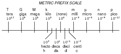
The metric system, besides being a collection of measurement units for all sorts of physical quantities, is structured around the concept of scientific notation. The primary difference is that the powers-of-ten are represented with alphabetical prefixes instead of by literal powers-of-ten. The following number line shows some of the more common prefixes and their respective powers-of-ten:
Looking at this scale, we can see that 2.5 Gigabytes would mean 2.5 x 109 bytes, or 2.5 billion bytes. Likewise, 3.21 picoamps would mean 3.21 x 10⁻¹² amps, or 3.21 1/trillionths of an amp.
Other metric prefixes exist to symbolize powers of ten for extremely small and extremely large multipliers. On the extremely small end of the spectrum, femto (f) = 10-15, atto (a) = 10-18, zepto (z) = 10-21, and yocto (y) = 10-24. On the extremely large end of the spectrum, Peta (P) = 1015, Exa (E) = 1018, Zetta (Z) = 1021, and Yotta (Y) = 1024.
Because the major prefixes in the metric system refer to powers of 10 that are multiples of 3 (from “kilo” on up, and from “milli” on down), metric notation differs from regular scientific notation in that the mantissa can be anywhere between 1 and 999, depending on which prefix is chosen. For example, if a laboratory sample weighs 0.000267 grams, scientific notation and metric notation would express it differently:
2.67 x 10⁻⁴ grams (scientific notation)
267 µgrams (metric notation)
The same figure may also be expressed as 0.267 milligrams (0.267 mg), although it is usually more common to see the significant digits represented as a figure greater than 1.
In recent years a new style of metric notation for electric quantities has emerged which seeks to avoid the use of the decimal point. Since decimal points (“.”) are easily misread and/or “lost” due to poor print quality, quantities such as 4.7 k may be mistaken for 47 k. The new notation replaces the decimal point with the metric prefix character, so that “4.7 k” is printed instead as “4k7”. Our last figure from the prior example, “0.267 m”, would be expressed in the new notation as “0m267”.
REVIEW:
The metric system of notation uses alphabetical prefixes to represent certain powers-of-ten instead of the lengthier scientific notation.
Metric Prefix Conversions
To express a quantity in a different metric prefix that what it was originally given, all we need to do is skip the decimal point to the right or to the left as needed. Notice that the metric prefix “number line” in the previous section was laid out from larger to smaller, left to right. This layout was purposely chosen to make it easier to remember which direction you need to skip the decimal point for any given conversion.
Example problem: express 0.000023 amps in terms of microamps.
0.000023 amps (has no prefix, just plain unit of amps)
From UNITS to micro on the number line is 6 places (powers of ten) to the right, so we need to skip the decimal point 6 places to the right:
0.000023 amps = 23. , or 23 microamps (µA)
Example problem: express 304,212 volts in terms of kilovolts.
304,212 volts (has no prefix, just plain unit of volts)
From the (none) place to kilo place on the number line is 3 places (powers of ten) to the left, so we need to skip the decimal point 3 places to the left:
304,212. = 304.212 kilovolts (kV)
Example problem: express 50.3 Mega-ohms in terms of milli-ohms.
50.3 M ohms (mega = 106)
From mega to milli is 9 places (powers of ten) to the right (from 10 to the 6th power to 10 to the -3rd power), so we need to skip the decimal point 9 places to the right:
50.3 M ohms = 50,300,000,000 milli-ohms (mΩ)
REVIEW:
Follow the metric prefix number line to know which direction you skip the decimal point for conversion purposes.
A number with no decimal point shown has an implicit decimal point to the immediate right of the furthest right digit (i.e. for the number 436 the decimal point is to the right of the 6, as such: 436.)
Hand Calculator Use
To enter numbers in scientific notation into a hand calculator, there is usually a button marked “E” or “EE” used to enter the correct power of ten. For example, to enter the mass of a proton in grams (1.67 x 10⁻²⁴ grams) into a hand calculator, I would enter the following keystrokes:
[1] [.] [6] [7] [EE] [2] [4] [+/-]
The [+/-] keystroke changes the sign of the power (24) into a -24. Some calculators allow the use of the subtraction key [-] to do this, but I prefer the “change sign” [+/-] key because its more consistent with the use of that key in other contexts.
If I wanted to enter a negative number in scientific notation into a hand calculator, I would have to be careful how I used the [+/-] key, lest I change the sign of the power and not the significant digit value. Pay attention to this example:
Number to be entered: -3.221 x 10⁻¹⁵:
[3] [.] [2] [2] [1] [+/-] [EE] [1] [5] [+/-]
The first [+/-] keystroke changes the entry from 3.221 to -3.221; the second [+/-] keystroke changes the power from 15 to -15.
Displaying metric and scientific notation on a hand calculator is a different matter. It involves changing the display option from the normal “fixed” decimal point mode to the “scientific” or “engineering” mode. Your calculator manual will tell you how to set each display mode.
These display modes tell the calculator how to represent any number on the numerical readout. The actual value of the number is not affected in any way by the choice of display modes — only how the number appears to the calculator user. Likewise, the procedure for entering numbers into the calculator does not change with different display modes either. Powers of ten are usually represented by a pair of digits in the upper-right hand corner of the display, and are visible only in the “scientific” and “engineering” modes.
The difference between “scientific” and “engineering” display modes is the difference between scientific and metric notation. In “scientific” mode, the power-of-ten display is set so that the main number on the display is always a value between 1 and 10 (or -1 and -10 for negative numbers). In “engineering” mode, the powers-of-ten are set to display in multiples of 3, to represent the major metric prefixes. All the user has to do is memorize a few prefix/power combinations, and his or her calculator will be “speaking” metric!
POWER       METRIC PREFIX
-----       -------------
12 ......... Tera  (T)
9 .......... Giga  (G)
6 .......... Mega  (M)
3 .......... Kilo  (k)
0 .......... UNITS (plain)
-3 ......... milli (m)
-6 ......... micro (u)
-9 ......... nano  (n)
-12 ........ pico  (p)
REVIEW:
Use the [EE] key to enter powers of ten.
Use “scientific” or “engineering” to display powers of ten, in scientific or metric notation, respectively.
Scientific Notation in SPICE
The SPICE circuit simulation computer program uses scientific notation to display its output information, and can interpret both scientific notation and metric prefixes in the circuit description files. If you are going to be able to successfully interpret the SPICE analyses throughout this book, you must be able to understand the notation used to express variables of voltage, current, etc. in the program.
Let’s start with a very simple circuit composed of one voltage source (a battery) and one resistor:
To simulate this circuit using SPICE, we first have to designate node numbers for all the distinct points in the circuit, then list the components along with their respective node numbers so the computer knows which component is connected to which, and how. For a circuit of this simplicity, the use of SPICE seems like overkill, but it serves the purpose of demonstrating practical use of scientific notation:
Typing out a circuit description file, or netlist, for this circuit, we get this:
simple circuit
v1 1 0 dc 24
r1 1 0 5
.end
The line “v1 1 0 dc 24” describes the battery, positioned between nodes 1 and 0, with a DC voltage of 24 volts. The line “r1 1 0 5” describes the 5 Ω resistor placed between nodes 1 and 0.
Using a computer to run a SPICE analysis on this circuit description file, we get the following results:
node   voltage
(  1)   24.0000
voltage source currents

name       current
v1       -4.800E+00

total power dissipation   1.15E+02  watts
SPICE tells us that the voltage “at” node number 1 (actually, this means the voltage between nodes 1 and 0, node 0 being the default reference point for all voltage measurements) is equal to 24 volts. The current through battery “v1” is displayed as -4.800E+00 amps. This is SPICE’s method of denoting scientific notation. What its really saying is “-4.800 x 100 amps,” or simply -4.800 amps. The negative value for current here is due to a quirk in SPICE and does not indicate anything significant about the circuit itself. The “total power dissipation” is given to us as 1.15E+02 watts, which means “1.15 x 10² watts,” or 115 watts.
Let’s modify our example circuit so that it has a 5 kΩ (5 kilo-ohm, or 5,000 ohm) resistor instead of a 5 Ω resistor and see what happens.
Once again is our circuit description file, or “netlist:”
simple circuit
v1 1 0 dc 24
r1 1 0 5k
.end
The letter “k” following the number 5 on the resistor’s line tells SPICE that it is a figure of 5 kΩ, not 5 Ω. Let’s see what result we get when we run this through the computer:
node   voltage
(  1)   24.0000
voltage source currents

name       current
v1        -4.800E-03

total power dissipation   1.15E-01  watts
The battery voltage, of course, hasn’t changed since the first simulation: its still at 24 volts. The circuit current, on the other hand, is much less this time because we’ve made the resistor a larger value, making it more difficult for electrons to flow. SPICE tells us that the current this time is equal to -4.800E-03 amps, or -4.800 x 10⁻³ amps. This is equivalent to taking the number -4.8 and skipping the decimal point three places to the left.
Of course, if we recognize that 10-3 is the same as the metric prefix “milli,” we could write the figure as -4.8 milliamps, or -4.8 mA.
Looking at the “total power dissipation” given to us by SPICE on this second simulation, we see that it is 1.15E-01 watts, or 1.15 x 10⁻¹ watts. The power of -1 corresponds to the metric prefix “deci,” but generally we limit our use of metric prefixes in electronics to those associated with powers of ten that are multiples of three (ten to the power of . . . -12, -9, -6, -3, 3, 6, 9, 12, etc.). So, if we want to follow this convention, we must express this power dissipation figure as 0.115 watts or 115 milliwatts (115 mW) rather than 1.15 deciwatts (1.15 dW).
Perhaps the easiest way to convert a figure from scientific notation to common metric prefixes is with a scientific calculator set to the “engineering” or “metric” display mode. Just set the calculator for that display mode, type any scientific notation figure into it using the proper keystrokes (see your owner’s manual), press the “equals” or “enter” key, and it should display the same figure in engineering/metric notation.
Again, I’ll be using SPICE as a method of demonstrating circuit concepts throughout this book. Consequently, it is in your best interest to understand scientific notation so you can easily comprehend its output data format.
Contributors
Contributors to this chapter are listed in chronological order of their contributions, from most recent to first. See Appendix 2 (Contributor List) for dates and contact information.
Jason Starck (June 2000): HTML document formatting, which led to a much better-looking second edition.
Circuits consisting of just one battery and one load resistance are very simple to analyze, but they are not often found in practical applications. Usually, we find circuits where more than two components are connected together.
There are two basic ways in which to connect more than two circuit components: series and parallel. First, an example of a series circuit:
Here, we have three resistors (labeled R1, R2, and R3), connected in a long chain from one terminal of the battery to the other. (It should be noted that the subscript labeling — those little numbers to the lower-right of the letter “R” — are unrelated to the resistor values in ohms. They serve only to identify one resistor from another.) The defining characteristic of a series circuit is that there is only one path for electrons to flow. In this circuit the electrons flow in a counter-clockwise direction, from point 4 to point 3 to point 2 to point 1 and back around to 4.
Now, let’s look at the other type of circuit, a parallel configuration:
Again, we have three resistors, but this time they form more than one continuous path for electrons to flow. There’s one path from 8 to 7 to 2 to 1 and back to 8 again. There’s another from 8 to 7 to 6 to 3 to 2 to 1 and back to 8 again. And then there’s a third path from 8 to 7 to 6 to 5 to 4 to 3 to 2 to 1 and back to 8 again. Each individual path (through R1, R2, and R3) is called a branch.
The defining characteristic of a parallel circuit is that all components are connected between the same set of electrically common points. Looking at the schematic diagram, we see that points 1, 2, 3, and 4 are all electrically common. So are points 8, 7, 6, and 5. Note that all resistors as well as the battery are connected between these two sets of points.
And, of course, the complexity doesn’t stop at simple series and parallel either! We can have circuits that are a combination of series and parallel, too:
In this circuit, we have two loops for electrons to flow through: one from 6 to 5 to 2 to 1 and back to 6 again, and another from 6 to 5 to 4 to 3 to 2 to 1 and back to 6 again. Notice how both current paths go through R1 (from point 2 to point 1). In this configuration, we’d say that R2 and R3 are in parallel with each other, while R1 is in series with the parallel combination of R2 and R3.
This is just a preview of things to come. Don’t worry! We’ll explore all these circuit configurations in detail, one at a time!
The basic idea of a “series” connection is that components are connected end-to-end in a line to form a single path for electrons to flow:
The basic idea of a “parallel” connection, on the other hand, is that all components are connected across each other’s leads. In a purely parallel circuit, there are never more than two sets of electrically common points, no matter how many components are connected. There are many paths for electrons to flow, but only one voltage across all components:
Series and parallel resistor configurations have very different electrical properties. We’ll explore the properties of each configuration in the sections to come.
REVIEW:
In a series circuit, all components are connected end-to-end, forming a single path for electrons to flow.
In a parallel circuit, all components are connected across each other, forming exactly two sets of electrically common points.
A “branch” in a parallel circuit is a path for electric current formed by one of the load components (such as a resistor).
Simple Series Circuits
Let’s start with a series circuit consisting of three resistors and a single battery:
The first principle to understand about series circuits is that the amount of current is the same through any component in the circuit. This is because there is only one path for electrons to flow in a series circuit, and because free electrons flow through conductors like marbles in a tube, the rate of flow (marble speed) at any point in the circuit (tube) at any specific point in time must be equal.
From the way that the 9 volt battery is arranged, we can tell that the electrons in this circuit will flow in a counter-clockwise direction, from point 4 to 3 to 2 to 1 and back to 4. However, we have one source of voltage and three resistances. How do we use Ohm’s Law here?
An important caveat to Ohm’s Law is that all quantities (voltage, current, resistance, and power) must relate to each other in terms of the same two points in a circuit. For instance, with a single-battery, single-resistor circuit, we could easily calculate any quantity because they all applied to the same two points in the circuit:
Since points 1 and 2 are connected together with wire of negligible resistance, as are points 3 and 4, we can say that point 1 is electrically common to point 2, and that point 3 is electrically common to point 4. Since we know we have 9 volts of electromotive force between points 1 and 4 (directly across the battery), and since point 2 is common to point 1 and point 3 common to point 4, we must also have 9 volts between points 2 and 3 (directly across the resistor). Therefore, we can apply Ohm’s Law (I = E/R) to the current through the resistor, because we know the voltage (E) across the resistor and the resistance (R) of that resistor. All terms (E, I, R) apply to the same two points in the circuit, to that same resistor, so we can use the Ohm’s Law formula with no reservation.
However, in circuits containing more than one resistor, we must be careful in how we apply Ohm’s Law. In the three-resistor example circuit below, we know that we have 9 volts between points 1 and 4, which is the amount of electromotive force trying to push electrons through the series combination of R1, R2, and R3. However, we cannot take the value of 9 volts and divide it by 3k, 10k or 5k Ω to try to find a current value, because we don’t know how much voltage is across any one of those resistors, individually.
The figure of 9 volts is a total quantity for the whole circuit, whereas the figures of 3k, 10k, and 5k Ω are individual quantities for individual resistors. If we were to plug a figure for total voltage into an Ohm’s Law equation with a figure for individual resistance, the result would not relate accurately to any quantity in the real circuit.
For R1, Ohm’s Law will relate the amount of voltage across R1 with the current through R1, given R1‘s resistance, 3kΩ:
But, since we don’t know the voltage across R1 (only the total voltage supplied by the battery across the three-resistor series combination) and we don’t know the current through R1, we can’t do any calculations with either formula. The same goes for R2 and R3: we can apply the Ohm’s Law equations if and only if all terms are representative of their respective quantities between the same two points in the circuit.
So what can we do? We know the voltage of the source (9 volts) applied across the series combination of R1, R2, and R3, and we know the resistances of each resistor, but since those quantities aren’t in the same context, we can’t use Ohm’s Law to determine the circuit current. If only we knew what the total resistance was for the circuit: then we could calculate total current with our figure for total voltage (I=E/R).
This brings us to the second principle of series circuits: the total resistance of any series circuit is equal to the sum of the individual resistances. This should make intuitive sense: the more resistors in series that the electrons must flow through, the more difficult it will be for those electrons to flow. In the example problem, we had a 3 kΩ, 10 kΩ, and 5 kΩ resistor in series, giving us a total resistance of 18 kΩ:
In essence, we’ve calculated the equivalent resistance of R1, R2, and R3 combined. Knowing this, we could re-draw the circuit with a single equivalent resistor representing the series combination of R1, R2, and R3:
Now we have all the necessary information to calculate circuit current, because we have the voltage between points 1 and 4 (9 volts) and the resistance between points 1 and 4 (18 kΩ):
Knowing that current is equal through all components of a series circuit (and we just determined the current through the battery), we can go back to our original circuit schematic and note the current through each component:
Now that we know the amount of current through each resistor, we can use Ohm’s Law to determine the voltage drop across each one (applying Ohm’s Law in its proper context):
Notice the voltage drops across each resistor, and how the sum of the voltage drops (1.5 + 5 + 2.5) is equal to the battery (supply) voltage: 9 volts. This is the third principle of series circuits: that the supply voltage is equal to the sum of the individual voltage drops.
However, the method we just used to analyze this simple series circuit can be streamlined for better understanding. By using a table to list all voltages, currents, and resistances in the circuit, it becomes very easy to see which of those quantities can be properly related in any Ohm’s Law equation:
The rule with such a table is to apply Ohm’s Law only to the values within each vertical column. For instance, ER1 only with IR1 and R1; ER2 only with IR2 and R2; etc. You begin your analysis by filling in those elements of the table that are given to you from the beginning:
As you can see from the arrangement of the data, we can’t apply the 9 volts of ET (total voltage) to any of the resistances (R1, R2, or R3) in any Ohm’s Law formula because they’re in different columns. The 9 volts of battery voltage is not applied directly across R1, R2, or R3. However, we can use our “rules” of series circuits to fill in blank spots on a horizontal row. In this case, we can use the series rule of resistances to determine a total resistance from the sum of individual resistances:
Now, with a value for total resistance inserted into the rightmost (“Total”) column, we can apply Ohm’s Law of I=E/R to total voltage and total resistance to arrive at a total current of 500 µA:
Then, knowing that the current is shared equally by all components of a series circuit (another “rule” of series circuits), we can fill in the currents for each resistor from the current figure just calculated:
Finally, we can use Ohm’s Law to determine the voltage drop across each resistor, one column at a time:
Just for fun, we can use a computer to analyze this very same circuit automatically. It will be a good way to verify our calculations and also become more familiar with computer analysis. First, we have to describe the circuit to the computer in a format recognizable by the software. The SPICE program we’ll be using requires that all electrically unique points in a circuit be numbered, and component placement is understood by which of those numbered points, or “nodes,” they share. For clarity, I numbered the four corners of our example circuit 1 through 4. SPICE, however, demands that there be a node zero somewhere in the circuit, so I’ll re-draw the circuit, changing the numbering scheme slightly:
All I’ve done here is re-numbered the lower-left corner of the circuit 0 instead of 4. Now, I can enter several lines of text into a computer file describing the circuit in terms SPICE will understand, complete with a couple of extra lines of code directing the program to display voltage and current data for our viewing pleasure. This computer file is known as the netlist in SPICE terminology:
This printout is telling us the battery voltage is 9 volts, and the voltage drops across R1, R2, and R3 are 1.5 volts, 5 volts, and 2.5 volts, respectively. Voltage drops across any component in SPICE are referenced by the node numbers the component lies between, so v(1,2) is referencing the voltage between nodes 1 and 2 in the circuit, which are the points between which R1 is located. The order of node numbers is important: when SPICE outputs a figure for v(1,2), it regards the polarity the same way as if we were holding a voltmeter with the red test lead on node 1 and the black test lead on node 2.
We also have a display showing current (albeit with a negative value) at 0.5 milliamps, or 500 microamps. So our mathematical analysis has been vindicated by the computer. This figure appears as a negative number in the SPICE analysis, due to a quirk in the way SPICE handles current calculations.
In summary, a series circuit is defined as having only one path for electrons to flow. From this definition, three rules of series circuits follow: all components share the same current; resistances add to equal a larger, total resistance; and voltage drops add to equal a larger, total voltage. All of these rules find root in the definition of a series circuit. If you understand that definition fully, then the rules are nothing more than footnotes to the definition.
REVIEW:
Components in a series circuit share the same current: ITotal = I1 = I2 = . . . In
Total resistance in a series circuit is equal to the sum of the individual resistances: RTotal = R1 + R2 + . . . Rn
Total voltage in a series circuit is equal to the sum of the individual voltage drops: ETotal = E1 + E2 + . . . En
Simple Parallel Circuits
Lessons In Electric Circuits copyright (C) 2000-2020 Tony R. Kuphaldt, under the terms and conditions of the Design Science License.
Let’s start with a parallel circuit consisting of three resistors and a single battery:
The first principle to understand about parallel circuits is that the voltage is equal across all components in the circuit. This is because there are only two sets of electrically common points in a parallel circuit, and voltage measured between sets of common points must always be the same at any given time. Therefore, in the above circuit, the voltage across R1 is equal to the voltage across R2 which is equal to the voltage across R3 which is equal to the voltage across the battery. This equality of voltages can be represented in another table for our starting values:
Just as in the case of series circuits, the same caveat for Ohm’s Law applies: values for voltage, current, and resistance must be in the same context in order for the calculations to work correctly. However, in the above example circuit, we can immediately apply Ohm’s Law to each resistor to find its current because we know the voltage across each resistor (9 volts) and the resistance of each resistor:
At this point we still don’t know what the total current or total resistance for this parallel circuit is, so we can’t apply Ohm’s Law to the rightmost (“Total”) column. However, if we think carefully about what is happening it should become apparent that the total current must equal the sum of all individual resistor (“branch”) currents:
As the total current exits the negative (-) battery terminal at point 8 and travels through the circuit, some of the flow splits off at point 7 to go up through R1, some more splits off at point 6 to go up through R2, and the remainder goes up through R3. Like a river branching into several smaller streams, the combined flow rates of all streams must equal the flow rate of the whole river. The same thing is encountered where the currents through R1, R2, and R3 join to flow back to the positive terminal of the battery (+) toward point 1: the flow of electrons from point 2 to point 1 must equal the sum of the (branch) currents through R1, R2, and R3.
This is the second principle of parallel circuits: the total circuit current is equal to the sum of the individual branch currents. Using this principle, we can fill in the IT spot on our table with the sum of IR1, IR2, and IR3:
Finally, applying Ohm’s Law to the rightmost (“Total”) column, we can calculate the total circuit resistance:
Please note something very important here. The total circuit resistance is only 625 Ω: less than any one of the individual resistors. In the series circuit, where the total resistance was the sum of the individual resistances, the total was bound to be greater than any one of the resistors individually. Here in the parallel circuit, however, the opposite is true: we say that the individual resistances diminish rather than add to make the total. This principle completes our triad of “rules” for parallel circuits, just as series circuits were found to have three rules for voltage, current, and resistance. Mathematically, the relationship between total resistance and individual resistances in a parallel circuit looks like this:
The same basic form of equation works for any number of resistors connected together in parallel, just add as many 1/R terms on the denominator of the fraction as needed to accommodate all parallel resistors in the circuit.
Just as with the series circuit, we can use computer analysis to double-check our calculations. First, of course, we have to describe our example circuit to the computer in terms it can understand. I’ll start by re-drawing the circuit:
Once again we find that the original numbering scheme used to identify points in the circuit will have to be altered for the benefit of SPICE. In SPICE, all electrically common points must share identical node numbers. This is how SPICE knows what’s connected to what, and how. In a simple parallel circuit, all points are electrically common in one of two sets of points. For our example circuit, the wire connecting the tops of all the components will have one node number and the wire connecting the bottoms of the components will have the other. Staying true to the convention of including zero as a node number, I choose the numbers 0 and 1:
An example like this makes the rationale of node numbers in SPICE fairly clear to understand. By having all components share common sets of numbers, the computer “knows” they’re all connected in parallel with each other.
In order to display branch currents in SPICE, we need to insert zero-voltage sources in line (in series) with each resistor, and then reference our current measurements to those sources. For whatever reason, the creators of the SPICE program made it so that current could only be calculated through a voltage source. This is a somewhat annoying demand of the SPICE simulation program. With each of these “dummy” voltage sources added, some new node numbers must be created to connect them to their respective branch resistors:
The dummy voltage sources are all set at 0 volts so as to have no impact on the operation of the circuit. The circuit description file, or netlist, looks like this:
Parallel circuit
v1 1 0
r1 2 0 10k
r2 3 0 2k
r3 4 0 1k
vr1 1 2 dc 0
vr2 1 3 dc 0
vr3 1 4 dc 0
.dc v1 9 9 1
.print dc v(2,0) v(3,0) v(4,0)
.print dc i(vr1) i(vr2) i(vr3)
.end
Running the computer analysis, we get these results (I’ve annotated the printout with descriptive labels):
v1            v(2)        v(3)        v(4)
9.000E+00     9.000E+00   9.000E+00   9.000E+00
battery       R1 voltage  R2 voltage  R3 voltage
voltage
v1            i(vr1)      i(vr2)      i(vr3)
9.000E+00     9.000E-04   4.500E-03   9.000E-03
battery       R1 current  R2 current  R3 current
voltage
These values do indeed match those calculated through Ohm’s Law earlier: 0.9 mA for IR1, 4.5 mA for IR2, and 9 mA for IR3. Being connected in parallel, of course, all resistors have the same voltage dropped across them (9 volts, same as the battery).
In summary, a parallel circuit is defined as one where all components are connected between the same set of electrically common points. Another way of saying this is that all components are connected across each other’s terminals. From this definition, three rules of parallel circuits follow: all components share the same voltage; resistances diminish to equal a smaller, total resistance; and branch currents add to equal a larger, total current. Just as in the case of series circuits, all of these rules find root in the definition of a parallel circuit. If you understand that definition fully, then the rules are nothing more than footnotes to the definition.
REVIEW:
Components in a parallel circuit share the same voltage: ETotal = E1 = E2 = . . . En
Total resistance in a parallel circuit is less than any of the individual resistances: RTotal = 1 / (1/R1 + 1/R2 + . . . 1/Rn)
Total current in a parallel circuit is equal to the sum of the individual branch currents: ITotal = I1 + I2 + . . . In.
Conductance
When students first see the parallel resistance equation, the natural question to ask is, “Where did that thing come from?” It is truly an odd piece of arithmetic, and its origin deserves a good explanation.
Resistance, by definition, is the measure of friction a component presents to the flow of electrons through it. Resistance is symbolized by the capital letter “R” and is measured in the unit of “ohm.” However, we can also think of this electrical property in terms of its inverse: how easy it is for electrons to flow through a component, rather than how difficult. If resistance is the word we use to symbolize the measure of how difficult it is for electrons to flow, then a good word to express how easy it is for electrons to flow would be conductance.
Mathematically, conductance is the reciprocal, or inverse, of resistance:
The greater the resistance, the less the conductance, and vice versa. This should make intuitive sense, resistance and conductance being opposite ways to denote the same essential electrical property. If two components’ resistances are compared and it is found that component “A” has one-half the resistance of component “B,” then we could alternatively express this relationship by saying that component “A” is twice as conductive as component “B.” If component “A” has but one-third the resistance of component “B,” then we could say it is three times more conductive than component “B,” and so on.
Carrying this idea further, a symbol and unit were created to represent conductance. The symbol is the capital letter “G” and the unit is the mho, which is “ohm” spelled backwards (and you didn’t think electronics engineers had any sense of humor!). Despite its appropriateness, the unit of the mho was replaced in later years by the unit of siemens (abbreviated by the capital letter “S”). This decision to change unit names is reminiscent of the change from the temperature unit of degrees Centigrade to degrees Celsius, or the change from the unit of frequency c.p.s. (cycles per second) to Hertz. If you’re looking for a pattern here, Siemens, Celsius, and Hertz are all surnames of famous scientists, the names of which, sadly, tell us less about the nature of the units than the units’ original designations.
As a footnote, the unit of siemens is never expressed without the last letter “s.” In other words, there is no such thing as a unit of “siemen” as there is in the case of the “ohm” or the “mho.” The reason for this is the proper spelling of the respective scientists’ surnames. The unit for electrical resistance was named after someone named “Ohm,” whereas the unit for electrical conductance was named after someone named “Siemens,” therefore it would be improper to “singularize” the latter unit as its final “s” does not denote plurality.
Back to our parallel circuit example, we should be able to see that multiple paths (branches) for current reduces total resistance for the whole circuit, as electrons are able to flow easier through the whole network of multiple branches than through any one of those branch resistances alone. In terms of resistance, additional branches result in a lesser total (current meets with less opposition). In terms of conductance, however, additional branches results in a greater total (electrons flow with greater conductance):
Total parallel resistance is less than any one of the individual branch resistances because parallel resistors resist less together than they would separately:
Total parallel conductance is greater than any of the individual branch conductances because parallel resistors conduct better together than they would separately:
To be more precise, the total conductance in a parallel circuit is equal to the sum of the individual conductances:
If we know that conductance is nothing more than the mathematical reciprocal (1/x) of resistance, we can translate each term of the above formula into resistance by substituting the reciprocal of each respective conductance:
Solving the above equation for total resistance (instead of the reciprocal of total resistance), we can invert (reciprocate) both sides of the equation:
So, we arrive at our cryptic resistance formula at last! Conductance (G) is seldom used as a practical measurement, and so the above formula is a common one to see in the analysis of parallel circuits.
REVIEW:
Conductance is the opposite of resistance: the measure of how easy it is for electrons to flow through something.
Conductance is symbolized with the letter “G” and is measured in units of mhos or Siemens.
Mathematically, conductance equals the reciprocal of resistance: G = 1/R
Power Calculations
When calculating the power dissipation of resistive components, use any one of the three power equations to derive the answer from values of voltage, current, and/or resistance pertaining to each component:
This is easily managed by adding another row to our familiar table of voltages, currents, and resistances:
Power for any particular table column can be found by the appropriate Ohm’s Law equation (appropriate based on what figures are present for E, I, and R in that column).
An interesting rule for total power versus individual power is that it is additive for any configuration of circuit: series, parallel, series/parallel, or otherwise. Power is a measure of rate of work, and since power dissipated must equal the total power applied by the source(s) (as per the Law of Conservation of Energy in physics), circuit configuration has no effect on the mathematics.
REVIEW:
Power is additive in any configuration of resistive circuit: PTotal = P1 + P2 + . . . Pn
Correct Use of Ohm’s Law
One of the most common mistakes made by beginning electronics students in their application of Ohm’s Laws is mixing the contexts of voltage, current, and resistance. In other words, a student might mistakenly use a value for I through one resistor and the value for E across a set of interconnected resistors, thinking that they’ll arrive at the resistance of that one resistor. Not so! Remember this important rule: The variables used in Ohm’s Law equations must be common to the same two points in the circuit under consideration. I cannot overemphasize this rule. This is especially important in series-parallel combination circuits where nearby components may have different values for both voltage drop and current.
When using Ohm’s Law to calculate a variable pertaining to a single component, be sure the voltage you’re referencing is solely across that single component and the current you’re referencing is solely through that single component and the resistance you’re referencing is solely for that single component. Likewise, when calculating a variable pertaining to a set of components in a circuit, be sure that the voltage, current, and resistance values are specific to that complete set of components only! A good way to remember this is to pay close attention to the two points terminating the component or set of components being analyzed, making sure that the voltage in question is across those two points, that the current in question is the electron flow from one of those points all the way to the other point, that the resistance in question is the equivalent of a single resistor between those two points, and that the power in question is the total power dissipated by all components between those two points.
The “table” method presented for both series and parallel circuits in this chapter is a good way to keep the context of Ohm’s Law correct for any kind of circuit configuration. In a table like the one shown below, you are only allowed to apply an Ohm’s Law equation for the values of a single vertical column at a time:
Deriving values horizontally across columns is allowable as per the principles of series and parallel circuits:
Not only does the “table” method simplify the management of all relevant quantities, it also facilitates cross-checking of answers by making it easy to solve for the original unknown variables through other methods, or by working backwards to solve for the initially given values from your solutions. For example, if you have just solved for all unknown voltages, currents, and resistances in a circuit, you can check your work by adding a row at the bottom for power calculations on each resistor, seeing whether or not all the individual power values add up to the total power. If not, then you must have made a mistake somewhere! While this technique of “cross-checking” your work is nothing new, using the table to arrange all the data for the cross-check(s) results in a minimum of confusion.
REVIEW:
Apply Ohm’s Law to vertical columns in the table.
Apply rules of series/parallel to horizontal rows in the table.
Check your calculations by working “backwards” to try to arrive at originally given values (from your first calculated answers), or by solving for a quantity using more than one method (from different given values).
Component Failure Analysis
The job of a technician frequently entails “troubleshooting” (locating and correcting a problem) in malfunctioning circuits. Good troubleshooting is a demanding and rewarding effort, requiring a thorough understanding of the basic concepts, the ability to formulate hypotheses (proposed explanations of an effect), the ability to judge the value of different hypotheses based on their probability (how likely one particular cause may be over another), and a sense of creativity in applying a solution to rectify the problem. While it is possible to distill these skills into a scientific methodology, most practiced troubleshooters would agree that troubleshooting involves a touch of art, and that it can take years of experience to fully develop this art.
An essential skill to have is a ready and intuitive understanding of how component faults affect circuits in different configurations. We will explore some of the effects of component faults in both series and parallel circuits here, then to a greater degree at the end of the “Series-Parallel Combination Circuits” chapter.
Let’s start with a simple series circuit:
With all components in this circuit functioning at their proper values, we can mathematically determine all currents and voltage drops:
Now let us suppose that R2 fails shorted. Shorted means that the resistor now acts like a straight piece of wire, with little or no resistance. The circuit will behave as though a “jumper” wire were connected across R2 (in case you were wondering, “jumper wire” is a common term for a temporary wire connection in a circuit). What causes the shorted condition of R2 is no matter to us in this example; we only care about its effect upon the circuit:
With R2 shorted, either by a jumper wire or by an internal resistor failure, the total circuit resistance will decrease. Since the voltage output by the battery is a constant (at least in our ideal simulation here), a decrease in total circuit resistance means that total circuit current must increase:
As the circuit current increases from 20 milliamps to 60 milliamps, the voltage drops across R1 and R3 (which haven’t changed resistances) increase as well, so that the two resistors are dropping the whole 9 volts. R2, being bypassed by the very low resistance of the jumper wire, is effectively eliminated from the circuit, the resistance from one lead to the other having been reduced to zero. Thus, the voltage drop across R2, even with the increased total current, is zero volts.
On the other hand, if R2 were to fail “open” — resistance increasing to nearly infinite levels — it would also create wide-reaching effects in the rest of the circuit:
With R2 at infinite resistance and total resistance being the sum of all individual resistances in a series circuit, the total current decreases to zero. With zero circuit current, there is no electron flow to produce voltage drops across R1 or R3. R2, on the other hand, will manifest the full supply voltage across its terminals.
We can apply the same before/after analysis technique to parallel circuits as well. First, we determine what a “healthy” parallel circuit should behave like.
Supposing that R2 opens in this parallel circuit, here’s what the effects will be:
Notice that in this parallel circuit, an open branch only affects the current through that branch and the circuit’s total current. Total voltage — being shared equally across all components in a parallel circuit, will be the same for all resistors. Due to the fact that the voltage source’s tendency is to hold voltage constant, its voltage will not change, and being in parallel with all the resistors, it will hold all the resistors’ voltages the same as they were before: 9 volts. Being that voltage is the only common parameter in a parallel circuit, and the other resistors haven’t changed resistance value, their respective branch currents remain unchanged.
This is what happens in a household lamp circuit: all lamps get their operating voltage from power wiring arranged in a parallel fashion. Turning one lamp on and off (one branch in that parallel circuit closing and opening) doesn’t affect the operation of other lamps in the room, only the current in that one lamp (branch circuit) and the total current powering all the lamps in the room:
In an ideal case (with perfect voltage sources and zero-resistance connecting wire), shorted resistors in a simple parallel circuit will also have no effect on what’s happening in other branches of the circuit. In real life, the effect is not quite the same, and we’ll see why in the following example:
A shorted resistor (resistance of 0 Ω) would theoretically draw infinite current from any finite source of voltage (I=E/0). In this case, the zero resistance of R2 decreases the circuit total resistance to zero Ω as well, increasing total current to a value of infinity. As long as the voltage source holds steady at 9 volts, however, the other branch currents (IR1 and IR3) will remain unchanged.
The critical assumption in this “perfect” scheme, however, is that the voltage supply will hold steady at its rated voltage while supplying an infinite amount of current to a short-circuit load. This is simply not realistic. Even if the short has a small amount of resistance (as opposed to absolutely zero resistance), no real voltage source could arbitrarily supply a huge overload current and maintain steady voltage at the same time. This is primarily due to the internal resistance intrinsic to all electrical power sources, stemming from the inescapable physical properties of the materials they’re constructed of:
These internal resistances, small as they may be, turn our simple parallel circuit into a series-parallel combination circuit. Usually, the internal resistances of voltage sources are low enough that they can be safely ignored, but when high currents resulting from shorted components are encountered, their effects become very noticeable. In this case, a shorted R2 would result in almost all the voltage being dropped across the internal resistance of the battery, with almost no voltage left over for resistors R1, R2, and R3:
Suffice it to say, intentional direct short-circuits across the terminals of any voltage source is a bad idea. Even if the resulting high current (heat, flashes, sparks) causes no harm to people nearby, the voltage source will likely sustain damage, unless it has been specifically designed to handle short-circuits, which most voltage sources are not.
Eventually in this book I will lead you through the analysis of circuits without the use of any numbers, that is, analyzing the effects of component failure in a circuit without knowing exactly how many volts the battery produces, how many ohms of resistance is in each resistor, etc. This section serves as an introductory step to that kind of analysis.
Whereas the normal application of Ohm’s Law and the rules of series and parallel circuits is performed with numerical quantities (“quantitative”), this new kind of analysis without precise numerical figures is something I like to call qualitative analysis. In other words, we will be analyzing the qualities of the effects in a circuit rather than the precise quantities. The result, for you, will be a much deeper intuitive understanding of electric circuit operation.
REVIEW:
To determine what would happen in a circuit if a component fails, re-draw that circuit with the equivalent resistance of the failed component in place and re-calculate all values.
The ability to intuitively determine what will happen to a circuit with any given component fault is a crucial skill for any electronics troubleshooter to develop. The best way to learn is to experiment with circuit calculations and real-life circuits, paying close attention to what changes with a fault, what remains the same, and why!
A shorted component is one whose resistance has dramatically decreased.
An open component is one whose resistance has dramatically increased. For the record, resistors tend to fail open more often than fail shorted, and they almost never fail unless physically or electrically overstressed (physically abused or overheated).
Building Simple Resistor Circuits
In the course of learning about electricity, you will want to construct your own circuits using resistors and batteries. Some options are available in this matter of circuit assembly, some easier than others. In this section, I will explore a couple of fabrication techniques that will not only help you build the circuits shown in this chapter, but also more advanced circuits.
If all we wish to construct is a simple single-battery, single-resistor circuit, we may easily use alligator clip jumper wires like this:
Jumper wires with “alligator” style spring clips at each end provide a safe and convenient method of electrically joining components together.
If we wanted to build a simple series circuit with one battery and three resistors, the same “point-to-point” construction technique using jumper wires could be applied:
This technique, however, proves impractical for circuits much more complex than this, due to the awkwardness of the jumper wires and the physical fragility of their connections. A more common method of temporary construction for the hobbyist is the solderless breadboard, a device made of plastic with hundreds of spring-loaded connection sockets joining the inserted ends of components and/or 22-gauge solid wire pieces. A photograph of a real breadboard is shown here, followed by an illustration showing a simple series circuit constructed on one:
Underneath each hole in the breadboard face is a metal spring clip, designed to grasp any inserted wire or component lead. These metal spring clips are joined underneath the breadboard face, making connections between inserted leads. The connection pattern joins every five holes along a vertical column (as shown with the long axis of the breadboard situated horizontally):
Thus, when a wire or component lead is inserted into a hole on the breadboard, there are four more holes in that column providing potential connection points to other wires and/or component leads. The result is an extremely flexible platform for constructing temporary circuits. For example, the three-resistor circuit just shown could also be built on a breadboard like this:
A parallel circuit is also easy to construct on a solderless breadboard:
Breadboards have their limitations, though. First and foremost, they are intended for temporary construction only. If you pick up a breadboard, turn it upside-down, and shake it, any components plugged into it are sure to loosen, and may fall out of their respective holes. Also, breadboards are limited to fairly low-current (less than 1 amp) circuits. Those spring clips have a small contact area, and thus cannot support high currents without excessive heating.
For greater permanence, one might wish to choose soldering or wire-wrapping. These techniques involve fastening the components and wires to some structure providing a secure mechanical location (such as a phenolic or fiberglass board with holes drilled in it, much like a breadboard without the intrinsic spring-clip connections), and then attaching wires to the secured component leads. Soldering is a form of low-temperature welding, using a tin/lead or tin/silver alloy that melts to and electrically bonds copper objects. Wire ends soldered to component leads or to small, copper ring “pads” bonded on the surface of the circuit board serve to connect the components together. In wire wrapping, a small-gauge wire is tightly wrapped around component leads rather than soldered to leads or copper pads, the tension of the wrapped wire providing a sound mechanical and electrical junction to connect components together.
An example of a printed circuit board, or PCB, intended for hobbyist use is shown in this photograph:
This board appears copper-side-up: the side where all the soldering is done. Each hole is ringed with a small layer of copper metal for bonding to the solder. All holes are independent of each other on this particular board, unlike the holes on a solderless breadboard which are connected together in groups of five. Printed circuit boards with the same 5-hole connection pattern as breadboards can be purchased and used for hobby circuit construction, though.
Production printed circuit boards have traces of copper laid down on the phenolic or fiberglass substrate material to form pre-engineered connection pathways which function as wires in a circuit. An example of such a board is shown here, this unit actually a “power supply” circuit designed to take 120 volt alternating current (AC) power from a household wall socket and transform it into low-voltage direct current (DC). A resistor appears on this board, the fifth component counting up from the bottom, located in the middle-right area of the board.
A view of this board’s underside reveals the copper “traces” connecting components together, as well as the silver-colored deposits of solder bonding the component leads to those traces:
A soldered or wire-wrapped circuit is considered permanent: that is, it is unlikely to fall apart accidently. However, these construction techniques are sometimes considered too permanent. If anyone wishes to replace a component or change the circuit in any substantial way, they must invest a fair amount of time undoing the connections. Also, both soldering and wire-wrapping require specialized tools which may not be immediately available.
An alternative construction technique used throughout the industrial world is that of the terminal strip. Terminal strips, alternatively called barrier strips or terminal blocks, are comprised of a length of nonconducting material with several small bars of metal embedded within. Each metal bar has at least one machine screw or other fastener under which a wire or component lead may be secured. Multiple wires fastened by one screw are made electrically common to each other, as are wires fastened to multiple screws on the same bar. The following photograph shows one style of terminal strip, with a few wires attached.
Another, smaller terminal strip is shown in this next photograph. This type, sometimes referred to as a “European” style, has recessed screws to help prevent accidental shorting between terminals by a screwdriver or other metal object:
In the following illustration, a single-battery, three-resistor circuit is shown constructed on a terminal strip:
If the terminal strip uses machine screws to hold the component and wire ends, nothing but a screwdriver is needed to secure new connections or break old connections. Some terminal strips use spring-loaded clips — similar to a breadboard’s except for increased ruggedness — engaged and disengaged using a screwdriver as a push tool (no twisting involved). The electrical connections established by a terminal strip are quite robust, and are considered suitable for both permanent and temporary construction.
One of the essential skills for anyone interested in electricity and electronics is to be able to “translate” a schematic diagram to a real circuit layout where the components may not be oriented the same way. Schematic diagrams are usually drawn for maximum readability (excepting those few noteworthy examples sketched to create maximum confusion!), but practical circuit construction often demands a different component orientation. Building simple circuits on terminal strips is one way to develop the spatial-reasoning skill of “stretching” wires to make the same connection paths. Consider the case of a single-battery, three-resistor parallel circuit constructed on a terminal strip:
Progressing from a nice, neat, schematic diagram to the real circuit — especially when the resistors to be connected are physically arranged in a linear fashion on the terminal strip — is not obvious to many, so I’ll outline the process step-by-step. First, start with the clean schematic diagram and all components secured to the terminal strip, with no connecting wires:
Next, trace the wire connection from one side of the battery to the first component in the schematic, securing a connecting wire between the same two points on the real circuit. I find it helpful to over-draw the schematic’s wire with another line to indicate what connections I’ve made in real life:
Continue this process, wire by wire, until all connections in the schematic diagram have been accounted for. It might be helpful to regard common wires in a SPICE-like fashion: make all connections to a common wire in the circuit as one step, making sure each and every component with a connection to that wire actually has a connection to that wire before proceeding to the next. For the next step, I’ll show how the top sides of the remaining two resistors are connected together, being common with the wire secured in the previous step:
With the top sides of all resistors (as shown in the schematic) connected together, and to the battery’s positive (+) terminal, all we have to do now is connect the bottom sides together and to the other side of the battery:
Typically in industry, all wires are labeled with number tags, and electrically common wires bear the same tag number, just as they do in a SPICE simulation. In this case, we could label the wires 1 and 2:
Another industrial convention is to modify the schematic diagram slightly so as to indicate actual wire connection points on the terminal strip. This demands a labeling system for the strip itself: a “TB” number (terminal block number) for the strip, followed by another number representing each metal bar on the strip.
This way, the schematic may be used as a “map” to locate points in a real circuit, regardless of how tangled and complex the connecting wiring may appear to the eyes. This may seem excessive for the simple, three-resistor circuit shown here, but such detail is absolutely necessary for construction and maintenance of large circuits, especially when those circuits may span a great physical distance, using more than one terminal strip located in more than one panel or box.
REVIEW:
A solderless breadboard is a device used to quickly assemble temporary circuits by plugging wires and components into electrically common spring-clips arranged underneath rows of holes in a plastic board.
Soldering is a low-temperature welding process utilizing a lead/tin or tin/silver alloy to bond wires and component leads together, usually with the components secured to a fiberglass board.
Wire-wrapping is an alternative to soldering, involving small-gauge wire tightly wrapped around component leads rather than a welded joint to connect components together.
A terminal strip, also known as a barrier strip or terminal block is another device used to mount components and wires to build circuits. Screw terminals or heavy spring clips attached to metal bars provide connection points for the wire ends and component leads, these metal bars mounted separately to a piece of nonconducting material such as plastic, bakelite, or ceramic.
Contributors
Contributors to this chapter are listed in chronological order of their contributions, from most recent to first. See Appendix 2 (Contributor List) for dates and contact information.
Jason Starck (June 2000): HTML document formatting, which led to a much better-looking second edition.
Ron LaPlante (October 1998): helped create “table” method of series and parallel circuit analysis.
With this lesson, I hope to avoid a common mistake found in electronics textbooks of either ignoring or not covering with sufficient detail the subject of electrical safety. I assume that whoever reads this book has at least a passing interest in actually working with electricity, and as such the topic of safety is of paramount importance. Those authors, editors, and publishers who fail to incorporate this subject into their introductory texts are depriving the reader of life-saving information.
As an instructor of industrial electronics, I spend a full week with my students reviewing the theoretical and practical aspects of electrical safety. The same textbooks I found lacking in technical clarity I also found lacking in coverage of electrical safety, hence the creation of this chapter. Its placement after the first two chapters is intentional: in order for the concepts of electrical safety to make the most sense, some foundational knowledge of electricity is necessary.
Another benefit of including a detailed lesson on electrical safety is the practical context it sets for basic concepts of voltage, current, resistance, and circuit design. The more relevant a technical topic can be made, the more likely a student will be to pay attention and comprehend. And what could be more relevant than application to your own personal safety? Also, with electrical power being such an everyday presence in modern life, almost anyone can relate to the illustrations given in such a lesson. Have you ever wondered why birds don’t get shocked while resting on power lines? Read on and find out!
Most of us have experienced some form of electric “shock,” where electricity causes our body to experience pain or trauma. If we are fortunate, the extent of that experience is limited to tingles or jolts of pain from static electricity buildup discharging through our bodies. When we are working around electric circuits capable of delivering high power to loads, electric shock becomes a much more serious issue, and pain is the least significant result of shock.
As electric current is conducted through a material, any opposition to that flow of electrons (resistance) results in a dissipation of energy, usually in the form of heat. This is the most basic and easy-to-understand effect of electricity on living tissue: current makes it heat up. If the amount of heat generated is sufficient, the tissue may be burnt. The effect is physiologically the same as damage caused by an open flame or other high-temperature source of heat, except that electricity has the ability to burn tissue well beneath the skin of a victim, even burning internal organs.
Another effect of electric current on the body, perhaps the most significant in terms of hazard, regards the nervous system. By “nervous system” I mean the network of special cells in the body called “nerve cells” or “neurons” which process and conduct the multitude of signals responsible for regulation of many body functions. The brain, spinal cord, and sensory/motor organs in the body function together to allow it to sense, move, respond, think, and remember.
Nerve cells communicate to each other by acting as “transducers:” creating electrical signals (very small voltages and currents) in response to the input of certain chemical compounds called neurotransmitters, and releasing neurotransmitters when stimulated by electrical signals. If electric current of sufficient magnitude is conducted through a living creature (human or otherwise), its effect will be to override the tiny electrical impulses normally generated by the neurons, overloading the nervous system and preventing both reflex and volitional signals from being able to actuate muscles. Muscles triggered by an external (shock) current will involuntarily contract, and there’s nothing the victim can do about it.
This problem is especially dangerous if the victim contacts an energized conductor with his or her hands. The forearm muscles responsible for bending fingers tend to be better developed than those muscles responsible for extending fingers, and so if both sets of muscles try to contract because of an electric current conducted through the person’s arm, the “bending” muscles will win, clenching the fingers into a fist. If the conductor delivering current to the victim faces the palm of his or her hand, this clenching action will force the hand to grasp the wire firmly, thus worsening the situation by securing excellent contact with the wire. The victim will be completely unable to let go of the wire.
Medically, this condition of involuntary muscle contraction is called tetanus. Electricians familiar with this effect of electric shock often refer to an immobilized victim of electric shock as being “froze on the circuit.” Shock-induced tetanus can only be interrupted by stopping the current through the victim.
Even when the current is stopped, the victim may not regain voluntary control over their muscles for a while, as the neurotransmitter chemistry has been thrown into disarray. This principle has been applied in “stun gun” devices such as Tasers, which on the principle of momentarily shocking a victim with a high-voltage pulse delivered between two electrodes. A well-placed shock has the effect of temporarily (a few minutes) immobilizing the victim.
Electric current is able to affect more than just skeletal muscles in a shock victim, however. The diaphragm muscle controlling the lungs, and the heart — which is a muscle in itself — can also be “frozen” in a state of tetanus by electric current. Even currents too low to induce tetanus are often able to scramble nerve cell signals enough that the heart cannot beat properly, sending the heart into a condition known as fibrillation. A fibrillating heart flutters rather than beats, and is ineffective at pumping blood to vital organs in the body. In any case, death from asphyxiation and/or cardiac arrest will surely result from a strong enough electric current through the body. Ironically, medical personnel use a strong jolt of electric current applied across the chest of a victim to “jump start” a fibrillating heart into a normal beating pattern.
That last detail leads us into another hazard of electric shock, this one peculiar to public power systems. Though our initial study of electric circuits will focus almost exclusively on DC (Direct Current, or electricity that moves in a continuous direction in a circuit), modern power systems utilize alternating current, or AC. The technical reasons for this preference of AC over DC in power systems are irrelevant to this discussion, but the special hazards of each kind of electrical power are very important to the topic of safety.
How AC affects the body depends largely on frequency. Low-frequency (50- to 60-Hz) AC is used in US (60 Hz) and European (50 Hz) households; it can be more dangerous than high-frequency AC and is 3 to 5 times more dangerous than DC of the same voltage and amperage. Low-frequency AC produces extended muscle contraction (tetany), which may freeze the hand to the current’s source, prolonging exposure. DC is most likely to cause a single convulsive contraction, which often forces the victim away from the current’s source. [MMOM]
AC’s alternating nature has a greater tendency to throw the heart’s pacemaker neurons into a condition of fibrillation, whereas DC tends to just make the heart stand still. Once the shock current is halted, a “frozen” heart has a better chance of regaining a normal beat pattern than a fibrillating heart. This is why “defibrillating” equipment used by emergency medics works: the jolt of current supplied by the defibrillator unit is DC, which halts fibrillation and gives the heart a chance to recover.
In either case, electric currents high enough to cause involuntary muscle action are dangerous and are to be avoided at all costs. In the next section, we’ll take a look at how such currents typically enter and exit the body, and examine precautions against such occurrences.
REVIEW:
Electric current is capable of producing deep and severe burns in the body due to power dissipation across the body’s electrical resistance.
Tetanus is the condition where muscles involuntarily contract due to the passage of external electric current through the body. When involuntary contraction of muscles controlling the fingers causes a victim to be unable to let go of an energized conductor, the victim is said to be “froze on the circuit.”
Diaphragm (lung) and heart muscles are similarly affected by electric current. Even currents too small to induce tetanus can be strong enough to interfere with the heart’s pacemaker neurons, causing the heart to flutter instead of strongly beat.
Direct current (DC) is more likely to cause muscle tetanus than alternating current (AC), making DC more likely to “freeze” a victim in a shock scenario. However, AC is more likely to cause a victim’s heart to fibrillate, which is a more dangerous condition for the victim after the shocking current has been halted.
As we’ve already learned, electricity requires a complete path (circuit) to continuously flow. This is why the shock received from static electricity is only a momentary jolt: the flow of electrons is necessarily brief when static charges are equalized between two objects. Shocks of self-limited duration like this are rarely hazardous.
Without two contact points on the body for current to enter and exit, respectively, there is no hazard of shock. This is why birds can safely rest on high-voltage power lines without getting shocked: they make contact with the circuit at only one point.
In order for electrons to flow through a conductor, there must be a voltage present to motivate them. Voltage, as you should recall, is always relative between two points. There is no such thing as voltage “on” or “at” a single point in the circuit, and so the bird contacting a single point in the above circuit has no voltage applied across its body to establish a current through it. Yes, even though they rest on two feet, both feet are touching the same wire, making them electrically common. Electrically speaking, both of the bird’s feet touch the same point, hence there is no voltage between them to motivate current through the bird’s body.
This might lend one to believe that its impossible to be shocked by electricity by only touching a single wire. Like the birds, if we’re sure to touch only one wire at a time, we’ll be safe, right? Unfortunately, this is not correct. Unlike birds, people are usually standing on the ground when they contact a “live” wire. Many times, one side of a power system will be intentionally connected to earth ground, and so the person touching a single wire is actually making contact between two points in the circuit (the wire and earth ground):
The ground symbol is that set of three horizontal bars of decreasing width located at the lower-left of the circuit shown, and also at the foot of the person being shocked. In real life the power system ground consists of some kind of metallic conductor buried deep in the ground for making maximum contact with the earth. That conductor is electrically connected to an appropriate connection point on the circuit with thick wire. The victim’s ground connection is through their feet, which are touching the earth.
A few questions usually arise at this point in the mind of the student:
If the presence of a ground point in the circuit provides an easy point of contact for someone to get shocked, why have it in the circuit at all? Wouldn’t a ground-less circuit be safer?
The person getting shocked probably isn’t bare-footed. If rubber and fabric are insulating materials, then why aren’t their shoes protecting them by preventing a circuit from forming?
How good of a conductor can dirt be? If you can get shocked by current through the earth, why not use the earth as a conductor in our power circuits?
In answer to the first question, the presence of an intentional “grounding” point in an electric circuit is intended to ensure that one side of it is safe to come in contact with. Note that if our victim in the above diagram were to touch the bottom side of the resistor, nothing would happen even though their feet would still be contacting ground:
Because the bottom side of the circuit is firmly connected to ground through the grounding point on the lower-left of the circuit, the lower conductor of the circuit is made electrically common with earth ground. Since there can be no voltage between electrically common points, there will be no voltage applied across the person contacting the lower wire, and they will not receive a shock. For the same reason, the wire connecting the circuit to the grounding rod/plates is usually left bare (no insulation), so that any metal object it brushes up against will similarly be electrically common with the earth.
Circuit grounding ensures that at least one point in the circuit will be safe to touch. But what about leaving a circuit completely ungrounded? Wouldn’t that make any person touching just a single wire as safe as the bird sitting on just one? Ideally, yes. Practically, no. Observe what happens with no ground at all:
Despite the fact that the person’s feet are still contacting ground, any single point in the circuit should be safe to touch. Since there is no complete path (circuit) formed through the person’s body from the bottom side of the voltage source to the top, there is no way for a current to be established through the person. However, this could all change with an accidental ground, such as a tree branch touching a power line and providing connection to earth ground:
Such an accidental connection between a power system conductor and the earth (ground) is called a ground fault. Ground faults may be caused by many things, including dirt buildup on power line insulators (creating a dirty-water path for current from the conductor to the pole, and to the ground, when it rains), ground water infiltration in buried power line conductors, and birds landing on power lines, bridging the line to the pole with their wings. Given the many causes of ground faults, they tend to be unpredicatable. In the case of trees, no one can guarantee which wire their branches might touch. If a tree were to brush up against the top wire in the circuit, it would make the top wire safe to touch and the bottom one dangerous — just the opposite of the previous scenario where the tree contacts the bottom wire:
With a tree branch contacting the top wire, that wire becomes the grounded conductor in the circuit, electrically common with earth ground. Therefore, there is no voltage between that wire and ground, but full (high) voltage between the bottom wire and ground. As mentioned previously, tree branches are only one potential source of ground faults in a power system. Consider an ungrounded power system with no trees in contact, but this time with two people touching single wires:
With each person standing on the ground, contacting different points in the circuit, a path for shock current is made through one person, through the earth, and through the other person. Even though each person thinks they’re safe in only touching a single point in the circuit, their combined actions create a deadly scenario. In effect, one person acts as the ground fault which makes it unsafe for the other person. This is exactly why ungrounded power systems are dangerous: the voltage between any point in the circuit and ground (earth) is unpredictable, because a ground fault could appear at any point in the circuit at any time. The only character guaranteed to be safe in these scenarios is the bird, who has no connection to earth ground at all! By firmly connecting a designated point in the circuit to earth ground (“grounding” the circuit), at least safety can be assured at that one point. This is more assurance of safety than having no ground connection at all.
In answer to the second question, rubber-soled shoes do indeed provide some electrical insulation to help protect someone from conducting shock current through their feet. However, most common shoe designs are not intended to be electrically “safe,” their soles being too thin and not of the right substance. Also, any moisture, dirt, or conductive salts from body sweat on the surface of or permeated through the soles of shoes will compromise what little insulating value the shoe had to begin with. There are shoes specifically made for dangerous electrical work, as well as thick rubber mats made to stand on while working on live circuits, but these special pieces of gear must be in absolutely clean, dry condition in order to be effective. Suffice it to say, normal footwear is not enough to guarantee protection against electric shock from a power system.
Research conducted on contact resistance between parts of the human body and points of contact (such as the ground) shows a wide range of figures (see end of chapter for information on the source of this data):
Hand or foot contact, insulated with rubber: 20 MΩ typical.
Foot contact through leather shoe sole (dry): 100 kΩ to 500 kΩ
Foot contact through leather shoe sole (wet): 5 kΩ to 20 kΩ
As you can see, not only is rubber a far better insulating material than leather, but the presence of water in a porous substance such as leather greatly reduces electrical resistance.
In answer to the third question, dirt is not a very good conductor (at least not when its dry!). It is too poor of a conductor to support continuous current for powering a load. However, as we will see in the next section, it takes very little current to injure or kill a human being, so even the poor conductivity of dirt is enough to provide a path for deadly current when there is sufficient voltage available, as there usually is in power systems.
Some ground surfaces are better insulators than others. Asphalt, for instance, being oil-based, has a much greater resistance than most forms of dirt or rock. Concrete, on the other hand, tends to have fairly low resistance due to its intrinsic water and electrolyte (conductive chemical) content.
REVIEW:
Electric shock can only occur when contact is made between two points of a circuit; when voltage is applied across a victim’s body.
Power circuits usually have a designated point that is “grounded:” firmly connected to metal rods or plates buried in the dirt to ensure that one side of the circuit is always at ground potential (zero voltage between that point and earth ground).
A ground fault is an accidental connection between a circuit conductor and the earth (ground).
Special, insulated shoes and mats are made to protect persons from shock via ground conduction, but even these pieces of gear must be in clean, dry condition to be effective. Normal footwear is not good enough to provide protection from shock by insulating its wearer from the earth.
Though dirt is a poor conductor, it can conduct enough current to injure or kill a human being.
A common phrase heard in reference to electrical safety goes something like this: “It’s not voltage that kills, its current!” While there is an element of truth to this, there’s more to understand about shock hazard than this simple adage. If voltage presented no danger, no one would ever print and display signs saying: DANGER — HIGH VOLTAGE!
The principle that “current kills” is essentially correct. It is electric current that burns tissue, freezes muscles, and fibrillates hearts. However, electric current doesn’t just occur on its own: there must be voltage available to motivate electrons to flow through a victim. A person’s body also presents resistance to current, which must be taken into account.
Taking Ohm’s Law for voltage, current, and resistance, and expressing it in terms of current for a given voltage and resistance, we have this equation:
The amount of current through a body is equal to the amount of voltage applied between two points on that body, divided by the electrical resistance offered by the body between those two points. Obviously, the more voltage available to cause electrons to flow, the easier they will flow through any given amount of resistance. Hence, the danger of high voltage: high voltage means potential for large amounts of current through your body, which will injure or kill you. Conversely, the more resistance a body offers to current, the slower electrons will flow for any given amount of voltage. Just how much voltage is dangerous depends on how much total resistance is in the circuit to oppose the flow of electrons.
Body resistance is not a fixed quantity. It varies from person to person and from time to time. There’s even a body fat measurement technique based on a measurement of electrical resistance between a person’s toes and fingers. Differing percentages of body fat give provide different resistances: just one variable affecting electrical resistance in the human body. In order for the technique to work accurately, the person must regulate their fluid intake for several hours prior to the test, indicating that body hydration is another factor impacting the body’s electrical resistance.
Body resistance also varies depending on how contact is made with the skin: is it from hand-to-hand, hand-to-foot, foot-to-foot, hand-to-elbow, etc.? Sweat, being rich in salts and minerals, is an excellent conductor of electricity for being a liquid. So is blood, with its similarly high content of conductive chemicals. Thus, contact with a wire made by a sweaty hand or open wound will offer much less resistance to current than contact made by clean, dry skin.
Measuring electrical resistance with a sensitive meter, I measure approximately 1 million ohms of resistance (1 MΩ) between my two hands, holding on to the meter’s metal probes between my fingers. The meter indicates less resistance when I squeeze the probes tightly and more resistance when I hold them loosely. Sitting here at my computer, typing these words, my hands are clean and dry. If I were working in some hot, dirty, industrial environment, the resistance between my hands would likely be much less, presenting less opposition to deadly current, and a greater threat of electrical shock.
But how much current is harmful? The answer to that question also depends on several factors. Individual body chemistry has a significant impact on how electric current affects an individual. Some people are highly sensitive to current, experiencing involuntary muscle contraction with shocks from static electricity. Others can draw large sparks from discharging static electricity and hardly feel it, much less experience a muscle spasm. Despite these differences, approximate guidelines have been developed through tests which indicate very little current being necessary to manifest harmful effects (again, see end of chapter for information on the source of this data). All current figures given in milliamps (a milliamp is equal to 1/1000 of an amp):
BODILY EFFECT     DIRECT CURRENT (DC)    60 Hz AC     10 kHz AC
---------------------------------------------------------------
Slight sensation     Men = 1.0 mA         0.4 mA        7 mA
felt at hand(s)    Women = 0.6 mA         0.3 mA        5 mA
---------------------------------------------------------------
Threshold of         Men = 5.2 mA         1.1 mA       12 mA
perception         Women = 3.5 mA         0.7 mA        8 mA
---------------------------------------------------------------
Painful, but          Men = 62 mA           9 mA       55 mA
voluntary muscle    Women = 41 mA           6 mA       37 mA
control maintained
---------------------------------------------------------------
Painful, unable       Men = 76 mA          16 mA       75 mA
to let go of wires  Women = 51 mA        10.5 mA       50 mA
---------------------------------------------------------------
Severe pain,          Men = 90 mA          23 mA       94 mA
difficulty          Women = 60 mA          15 mA       63 mA
breathing
---------------------------------------------------------------
Possible heart        Men = 500 mA        100 mA
fibrillation        Women = 500 mA        100 mA
after 3 seconds
---------------------------------------------------------------
“Hz” stands for the unit of Hertz, the measure of how rapidly alternating current alternates, a measure otherwise known as frequency. So, the column of figures labeled “60 Hz AC” refers to current that alternates at a frequency of 60 cycles (1 cycle = period of time where electrons flow one direction, then the other direction) per second. The last column, labeled “10 kHz AC,” refers to alternating current that completes ten thousand (10,000) back-and-forth cycles each and every second.
Keep in mind that these figures are only approximate, as individuals with different body chemistry may react differently. It has been suggested that an across-the-chest current of only 17 milliamps AC is enough to induce fibrillation in a human subject under certain conditions. Most of our data regarding induced fibrillation comes from animal testing. Obviously, it is not practical to perform tests of induced ventricular fibrillation on human subjects, so the available data is sketchy. Oh, and in case you’re wondering, I have no idea why women tend to be more susceptible to electric currents than men!
Suppose I were to place my two hands across the terminals of an AC voltage source at 60 Hz (60 cycles, or alternations back-and-forth, per second). How much voltage would be necessary in this clean, dry state of skin condition to produce a current of 20 milliamps (enough to cause me to become unable to let go of the voltage source)? We can use Ohm’s Law (E=IR) to determine this:
E = IR
E = (20 mA)(1 MΩ)
E = 20,000 volts, or 20 kV
Bear in mind that this is a “best case” scenario (clean, dry skin) from the standpoint of electrical safety, and that this figure for voltage represents the amount necessary to induce tetanus. Far less would be required to cause a painful shock! Also keep in mind that the physiological effects of any particular amount of current can vary significantly from person to person, and that these calculations are rough estimates only.
With water sprinkled on my fingers to simulate sweat, I was able to measure a hand-to-hand resistance of only 17,000 ohms (17 kΩ). Bear in mind this is only with one finger of each hand contacting a thin metal wire. Recalculating the voltage required to cause a current of 20 milliamps, we obtain this figure:
E = IR
E = (20 mA)(17 kΩ)
E = 340 volts
In this realistic condition, it would only take 340 volts of potential from one of my hands to the other to cause 20 milliamps of current. However, it is still possible to receive a deadly shock from less voltage than this. Provided a much lower body resistance figure augmented by contact with a ring (a band of gold wrapped around the circumference of one’s finger makes an excellent contact point for electrical shock) or full contact with a large metal object such as a pipe or metal handle of a tool, the body resistance figure could drop as low as 1,000 ohms (1 kΩ), allowing an even lower voltage to present a potential hazard:
E = IR
E = (20 mA)(1 kΩ)
E = 20 volts
Notice that in this condition, 20 volts is enough to produce a current of 20 milliamps through a person: enough to induce tetanus. Remember, it has been suggested a current of only 17 milliamps may induce ventricular (heart) fibrillation. With a hand-to-hand resistance of 1000 Ω, it would only take 17 volts to create this dangerous condition:
E = IR
E = (17 mA)(1 kΩ)
E = 17 volts
Seventeen volts is not very much as far as electrical systems are concerned. Granted, this is a “worst-case” scenario with 60 Hz AC voltage and excellent bodily conductivity, but it does stand to show how little voltage may present a serious threat under certain conditions.
The conditions necessary to produce 1,000 Ω of body resistance don’t have to be as extreme as what was presented, either (sweaty skin with contact made on a gold ring). Body resistance may decrease with the application of voltage (especially if tetanus causes the victim to maintain a tighter grip on a conductor) so that with constant voltage a shock may increase in severity after initial contact. What begins as a mild shock — just enough to “freeze” a victim so they can’t let go — may escalate into something severe enough to kill them as their body resistance decreases and current correspondingly increases.
Research has provided an approximate set of figures for electrical resistance of human contact points under different conditions (see end of chapter for information on the source of this data):
Wire touched by finger: 40,000 Ω to 1,000,000 Ω dry, 4,000 Ω to 15,000 Ω wet.
Wire held by hand: 15,000 Ω to 50,000 Ω dry, 3,000 Ω to 5,000 Ω wet.
Metal pliers held by hand: 5,000 Ω to 10,000 Ω dry, 1,000 Ω to 3,000 Ω wet.
Contact with palm of hand: 3,000 Ω to 8,000 Ω dry, 1,000 Ω to 2,000 Ω wet.
1.5 inch metal pipe grasped by one hand: 1,000 Ω to 3,000 Ω dry, 500 Ω to 1,500 Ω wet.
1.5 inch metal pipe grasped by two hands: 500 Ω to 1,500 kΩ dry, 250 Ω to 750 Ω wet.
Hand immersed in conductive liquid: 200 Ω to 500 Ω.
Foot immersed in conductive liquid: 100 Ω to 300 Ω.
Note the resistance values of the two conditions involving a 1.5 inch metal pipe. The resistance measured with two hands grasping the pipe is exactly one-half the resistance of one hand grasping the pipe.
With two hands, the bodily contact area is twice as great as with one hand. This is an important lesson to learn: electrical resistance between any contacting objects diminishes with increased contact area, all other factors being equal. With two hands holding the pipe, electrons have two, parallel routes through which to flow from the pipe to the body (or vice-versa).
As we will see in a later chapter, parallel circuit pathways always result in less overall resistance than any single pathway considered alone.
In industry, 30 volts is generally considered to be a conservative threshold value for dangerous voltage. The cautious person should regard any voltage above 30 volts as threatening, not relying on normal body resistance for protection against shock. That being said, it is still an excellent idea to keep one’s hands clean and dry, and remove all metal jewelry when working around electricity. Even around lower voltages, metal jewelry can present a hazard by conducting enough current to burn the skin if brought into contact between two points in a circuit. Metal rings, especially, have been the cause of more than a few burnt fingers by bridging between points in a low-voltage, high-current circuit.
Also, voltages lower than 30 can be dangerous if they are enough to induce an unpleasant sensation, which may cause you to jerk and accidently come into contact across a higher voltage or some other hazard. I recall once working on a automobile on a hot summer day. I was wearing shorts, my bare leg contacting the chrome bumper of the vehicle as I tightened battery connections. When I touched my metal wrench to the positive (ungrounded) side of the 12 volt battery, I could feel a tingling sensation at the point where my leg was touching the bumper. The combination of firm contact with metal and my sweaty skin made it possible to feel a shock with only 12 volts of electrical potential.
Thankfully, nothing bad happened, but had the engine been running and the shock felt at my hand instead of my leg, I might have reflexively jerked my arm into the path of the rotating fan, or dropped the metal wrench across the battery terminals (producing large amounts of current through the wrench with lots of accompanying sparks). This illustrates another important lesson regarding electrical safety; that electric current itself may be an indirect cause of injury by causing you to jump or spasm parts of your body into harm’s way.
The path current takes through the human body makes a difference as to how harmful it is. Current will affect whatever muscles are in its path, and since the heart and lung (diaphragm) muscles are probably the most critical to one’s survival, shock paths traversing the chest are the most dangerous. This makes the hand-to-hand shock current path a very likely mode of injury and fatality.
To guard against such an occurrence, it is advisable to only use one hand to work on live circuits of hazardous voltage, keeping the other hand tucked into a pocket so as to not accidently touch anything. Of course, it is always safer to work on a circuit when it is unpowered, but this is not always practical or possible. For one-handed work, the right hand is generally preferred over the left for two reasons: most people are right-handed (thus granting additional coordination when working), and the heart is usually situated to the left of center in the chest cavity.
For those who are left-handed, this advice may not be the best. If such a person is sufficiently uncoordinated with their right hand, they may be placing themselves in greater danger by using the hand they’re least comfortable with, even if shock current through that hand might present more of a hazard to their heart. The relative hazard between shock through one hand or the other is probably less than the hazard of working with less than optimal coordination, so the choice of which hand to work with is best left to the individual.
The best protection against shock from a live circuit is resistance, and resistance can be added to the body through the use of insulated tools, gloves, boots, and other gear. Current in a circuit is a function of available voltage divided by the total resistance in the path of the flow. As we will investigate in greater detail later in this book, resistances have an additive effect when they’re stacked up so that there’s only one path for electrons to flow:
Now we’ll see an equivalent circuit for a person wearing insulated gloves and boots:
Because electric current must pass through the boot and the body and the glove to complete its circuit back to the battery, the combined total (sum) of these resistances opposes the flow of electrons to a greater degree than any of the resistances considered individually.
Safety is one of the reasons electrical wires are usually covered with plastic or rubber insulation: to vastly increase the amount of resistance between the conductor and whoever or whatever might contact it. Unfortunately, it would be prohibitively expensive to enclose power line conductors in sufficient insulation to provide safety in case of accidental contact, so safety is maintained by keeping those lines far enough out of reach so that no one can accidently touch them.
REVIEW:
Harm to the body is a function of the amount of shock current. Higher voltage allows for the production of higher, more dangerous currents. Resistance opposes current, making high resistance a good protective measure against shock.
Any voltage above 30 is generally considered to be capable of delivering dangerous shock currents.
Metal jewelry is definitely bad to wear when working around electric circuits. Rings, watchbands, necklaces, bracelets, and other such adornments provide excellent electrical contact with your body, and can conduct current themselves enough to produce skin burns, even with low voltages.
Low voltages can still be dangerous even if they’re too low to directly cause shock injury. They may be enough to startle the victim, causing them to jerk back and contact something more dangerous in the near vicinity.
When necessary to work on a “live” circuit, it is best to perform the work with one hand so as to prevent a deadly hand-to-hand (through the chest) shock current path.
If at all possible, shut off the power to a circuit before performing any work on it. You must secure all sources of harmful energy before a system may be considered safe to work on. In industry, securing a circuit, device, or system in this condition is commonly known as placing it in a Zero Energy State. The focus of this lesson is, of course, electrical safety. However, many of these principles apply to non-electrical systems as well.
Securing something in a Zero Energy State means ridding it of any sort of potential or stored energy, including but not limited to:
Dangerous voltage
Spring pressure
Hydraulic (liquid) pressure
Pneumatic (air) pressure
Suspended weight
Chemical energy (flammable or otherwise reactive substances)
Nuclear energy (radioactive or fissile substances)
Voltage by its very nature is a manifestation of potential energy. In the first chapter I even used elevated liquid as an analogy for the potential energy of voltage, having the capacity (potential) to produce current (flow), but not necessarily realizing that potential until a suitable path for flow has been established, and resistance to flow is overcome. A pair of wires with high voltage between them do not look or sound dangerous even though they harbor enough potential energy between them to push deadly amounts of current through your body. Even though that voltage isn’t presently doing anything, it has the potential to, and that potential must be neutralized before it is safe to physically contact those wires.
All properly designed circuits have “disconnect” switch mechanisms for securing voltage from a circuit. Sometimes these “disconnects” serve a dual purpose of automatically opening under excessive current conditions, in which case we call them “circuit breakers.” Other times, the disconnecting switches are strictly manually-operated devices with no automatic function. In either case, they are there for your protection and must be used properly. Please note that the disconnect device should be separate from the regular switch used to turn the device on and off. It is a safety switch, to be used only for securing the system in a Zero Energy State:
With the disconnect switch in the “open” position as shown (no continuity), the circuit is broken and no current will exist. There will be zero voltage across the load, and the full voltage of the source will be dropped across the open contacts of the disconnect switch. Note how there is no need for a disconnect switch in the lower conductor of the circuit. Because that side of the circuit is firmly connected to the earth (ground), it is electrically common with the earth and is best left that way. For maximum safety of personnel working on the load of this circuit, a temporary ground connection could be established on the top side of the load, to ensure that no voltage could ever be dropped across the load:
With the temporary ground connection in place, both sides of the load wiring are connected to ground, securing a Zero Energy State at the load.
Since a ground connection made on both sides of the load is electrically equivalent to short-circuiting across the load with a wire, that is another way of accomplishing the same goal of maximum safety:
Either way, both sides of the load will be electrically common to the earth, allowing for no voltage (potential energy) between either side of the load and the ground people stand on. This technique of temporarily grounding conductors in a de-energized power system is very common in maintenance work performed on high voltage power distribution systems.
A further benefit of this precaution is protection against the possibility of the disconnect switch being closed (turned “on” so that circuit continuity is established) while people are still contacting the load. The temporary wire connected across the load would create a short-circuit when the disconnect switch was closed, immediately tripping any overcurrent protection devices (circuit breakers or fuses) in the circuit, which would shut the power off again. Damage may very well be sustained by the disconnect switch if this were to happen, but the workers at the load are kept safe.
It would be good to mention at this point that overcurrent devices are not intended to provide protection against electric shock. Rather, they exist solely to protect conductors from overheating due to excessive currents. The temporary shorting wires just described would indeed cause any overcurrent devices in the circuit to “trip” if the disconnect switch were to be closed, but realize that electric shock protection is not the intended function of those devices. Their primary function would merely be leveraged for the purpose of worker protection with the shorting wire in place.
Since it is obviously important to be able to secure any disconnecting devices in the open (off) position and make sure they stay that way while work is being done on the circuit, there is need for a structured safety system to be put into place. Such a system is commonly used in industry and it is called Lock-out/Tag-out.
A lock-out/tag-out procedure works like this: all individuals working on a secured circuit have their own personal padlock or combination lock which they set on the control lever of a disconnect device prior to working on the system. Additionally, they must fill out and sign a tag which they hang from their lock describing the nature and duration of the work they intend to perform on the system. If there are multiple sources of energy to be “locked out” (multiple disconnects, both electrical and mechanical energy sources to be secured, etc.), the worker must use as many of his or her locks as necessary to secure power from the system before work begins. This way, the system is maintained in a Zero Energy State until every last lock is removed from all the disconnect and shutoff devices, and that means every last worker gives consent by removing their own personal locks. If the decision is made to re-energize the system and one person’s lock(s) still remain in place after everyone present removes theirs, the tag(s) will show who that person is and what it is they’re doing.
Even with a good lock-out/tag-out safety program in place, there is still need for diligence and common-sense precaution. This is especially true in industrial settings where a multitude of people may be working on a device or system at once. Some of those people might not know about proper lock-out/tag-out procedure, or might know about it but are too complacent to follow it. Don’t assume that everyone has followed the safety rules!
After an electrical system has been locked out and tagged with your own personal lock, you must then double-check to see if the voltage really has been secured in a zero state. One way to check is to see if the machine (or whatever it is that’s being worked on) will start up if the Start switch or button is actuated. If it starts, then you know you haven’t successfully secured the electrical power from it.
Additionally, you should always check for the presence of dangerous voltage with a measuring device before actually touching any conductors in the circuit. To be safest, you should follow this procedure of checking, using, and then checking your meter:
Check to see that your meter indicates properly on a known source of voltage.
Use your meter to test the locked-out circuit for any dangerous voltage.
Check your meter once more on a known source of voltage to see that it still indicates as it should.
While this may seem excessive or even paranoid, it is a proven technique for preventing electrical shock. I once had a meter fail to indicate voltage when it should have while checking a circuit to see if it was “dead.” Had I not used other means to check for the presence of voltage, I might not be alive today to write this. There’s always the chance that your voltage meter will be defective just when you need it to check for a dangerous condition. Following these steps will help ensure that you’re never misled into a deadly situation by a broken meter.
Finally, the electrical worker will arrive at a point in the safety check procedure where it is deemed safe to actually touch the conductor(s). Bear in mind that after all of the precautionary steps have taken, it is still possible (although very unlikely) that a dangerous voltage may be present. One final precautionary measure to take at this point is to make momentary contact with the conductor(s) with the back of the hand before grasping it or a metal tool in contact with it. Why? If, for some reason there is still voltage present between that conductor and earth ground, finger motion from the shock reaction (clenching into a fist) will break contact with the conductor. Please note that this is absolutely the last step that any electrical worker should ever take before beginning work on a power system, and should never be used as an alternative method of checking for dangerous voltage. If you ever have reason to doubt the trustworthiness of your meter, use another meter to obtain a “second opinion.”
REVIEW:
Zero Energy State: When a circuit, device, or system has been secured so that no potential energy exists to harm someone working on it.
Disconnect switch devices must be present in a properly designed electrical system to allow for convenient readiness of a Zero Energy State.
Temporary grounding or shorting wires may be connected to a load being serviced for extra protection to personnel working on that load.
Lock-out/Tag-out works like this: when working on a system in a Zero Energy State, the worker places a personal padlock or combination lock on every energy disconnect device relevant to his or her task on that system. Also, a tag is hung on every one of those locks describing the nature and duration of the work to be done, and who is doing it.
Always verify that a circuit has been secured in a Zero Energy State with test equipment after “locking it out.” Be sure to test your meter before and after checking the circuit to verify that it is working properly.
When the time comes to actually make contact with the conductor(s) of a supposedly dead power system, do so first with the back of one hand, so that if a shock should occur, the muscle reaction will pull the fingers away from the conductor.
Despite lock-out/tag-out procedures and multiple repetitions of electrical safety rules in industry, accidents still do occur. The vast majority of the time, these accidents are the result of not following proper safety procedures. But however they may occur, they still do happen, and anyone working around electrical systems should be aware of what needs to be done for a victim of electrical shock.
If you see someone lying unconscious or “froze on the circuit,” the very first thing to do is shut off the power by opening the appropriate disconnect switch or circuit breaker. If someone touches another person being shocked, there may be enough voltage dropped across the body of the victim to shock the would-be rescuer, thereby “freezing” two people instead of one. Don’t be a hero. Electrons don’t respect heroism. Make sure the situation is safe for you to step into, or else you will be the next victim, and nobody will benefit from your efforts.
One problem with this rule is that the source of power may not be known, or easily found in time to save the victim of shock. If a shock victim’s breathing and heartbeat are paralyzed by electric current, their survival time is very limited. If the shock current is of sufficient magnitude, their flesh and internal organs may be quickly roasted by the power the current dissipates as it runs through their body.
If the power disconnect switch cannot be located quickly enough, it may be possible to dislodge the victim from the circuit they’re frozen on to by prying them or hitting them away with a dry wooden board or piece of nonmetallic conduit, common items to be found in industrial construction scenes. Another item that could be used to safely drag a “frozen” victim away from contact with power is an extension cord. By looping a cord around their torso and using it as a rope to pull them away from the circuit, their grip on the conductor(s) may be broken. Bear in mind that the victim will be holding on to the conductor with all their strength, so pulling them away probably won’t be easy!
Once the victim has been safely disconnected from the source of electric power, the immediate medical concerns for the victim should be respiration and circulation (breathing and pulse). If the rescuer is trained in CPR, they should follow the appropriate steps of checking for breathing and pulse, then applying CPR as necessary to keep the victim’s body from deoxygenating. The cardinal rule of CPR is to keep going until you have been relieved by qualified personnel.
If the victim is conscious, it is best to have them lie still until qualified emergency response personnel arrive on the scene. There is the possibility of the victim going into a state of physiological shock — a condition of insufficient blood circulation different from electrical shock — and so they should be kept as warm and comfortable as possible. An electrical shock insufficient to cause immediate interruption of the heartbeat may be strong enough to cause heart irregularities or a heart attack up to several hours later, so the victim should pay close attention to their own condition after the incident, ideally under supervision.
REVIEW:
A person being shocked needs to be disconnected from the source of electrical power. Locate the disconnecting switch/breaker and turn it off. Alternatively, if the disconnecting device cannot be located, the victim can be pried or pulled from the circuit by an insulated object such as a dry wood board, piece of nonmetallic conduit, or rubber electrical cord.
Victims need immediate medical response: check for breathing and pulse, then apply CPR as necessary to maintain oxygenation.
If a victim is still conscious after having been shocked, they need to be closely monitored and cared for until trained emergency response personnel arrive. There is danger of physiological shock, so keep the victim warm and comfortable.
Shock victims may suffer heart trouble up to several hours after being shocked. The danger of electric shock does not end after the immediate medical attention.
Of course there is danger of electrical shock when directly performing manual work on an electrical power system. However, electric shock hazards exist in many other places, thanks to the widespread use of electric power in our lives.
As we saw earlier, skin and body resistance has a lot to do with the relative hazard of electric circuits. The higher the body’s resistance, the less likely harmful current will result from any given amount of voltage. Conversely, the lower the body’s resistance, the more likely for injury to occur from the application of a voltage.
The easiest way to decrease skin resistance is to get it wet. Therefore, touching electrical devices with wet hands, wet feet, or especially in a sweaty condition (salt water is a much better conductor of electricity than fresh water) is dangerous. In the household, the bathroom is one of the more likely places where wet people may contact electrical appliances, and so shock hazard is a definite threat there. Good bathroom design will locate power receptacles away from bathtubs, showers, and sinks to discourage the use of appliances nearby. Telephones that plug into a wall socket are also sources of hazardous voltage (the open circuit voltage is 48 volts DC, and the ringing signal is 150 volts AC — remember that any voltage over 30 is considered potentially dangerous!). Appliances such as telephones and radios should never, ever be used while sitting in a bathtub. Even battery-powered devices should be avoided. Some battery-operated devices employ voltage-increasing circuitry capable of generating lethal potentials.
Swimming pools are another source of trouble, since people often operate radios and other powered appliances nearby. The National Electrical Code requires that special shock-detecting receptacles called Ground-Fault Current Interrupting (GFI or GFCI) be installed in wet and outdoor areas to help prevent shock incidents. More on these devices in a later section of this chapter. These special devices have no doubt saved many lives, but they can be no substitute for common sense and diligent precaution. As with firearms, the best “safety” is an informed and conscientious operator.
Extension cords, so commonly used at home and in industry, are also sources of potential hazard. All cords should be regularly inspected for abrasion or cracking of insulation, and repaired immediately. One sure method of removing a damaged cord from service is to unplug it from the receptacle, then cut off that plug (the “male” plug) with a pair of side-cutting pliers to ensure that no one can use it until it is fixed. This is important on jobsites, where many people share the same equipment, and not all people there may be aware of the hazards.
Any power tool showing evidence of electrical problems should be immediately serviced as well. I’ve heard several horror stories of people who continue to work with hand tools that periodically shock them. Remember, electricity can kill, and the death it brings can be gruesome. Like extension cords, a bad power tool can be removed from service by unplugging it and cutting off the plug at the end of the cord.
Downed power lines are an obvious source of electric shock hazard and should be avoided at all costs. The voltages present between power lines or between a power line and earth ground are typically very high (2400 volts being one of the lowest voltages used in residential distribution systems). If a power line is broken and the metal conductor falls to the ground, the immediate result will usually be a tremendous amount of arcing (sparks produced), often enough to dislodge chunks of concrete or asphalt from the road surface, and reports rivaling that of a rifle or shotgun. To come into direct contact with a downed power line is almost sure to cause death, but other hazards exist which are not so obvious.
When a line touches the ground, current travels between that downed conductor and the nearest grounding point in the system, thus establishing a circuit:
The earth, being a conductor (if only a poor one), will conduct current between the downed line and the nearest system ground point, which will be some kind of conductor buried in the ground for good contact. Being that the earth is a much poorer conductor of electricity than the metal cables strung along the power poles, there will be substantial voltage dropped between the point of cable contact with the ground and the grounding conductor, and little voltage dropped along the length of the cabling (the following figures are very approximate):
If the distance between the two ground contact points (the downed cable and the system ground) is small, there will be substantial voltage dropped along short distances between the two points. Therefore, a person standing on the ground between those two points will be in danger of receiving an electric shock by intercepting a voltage between their two feet!
Again, these voltage figures are very approximate, but they serve to illustrate a potential hazard: that a person can become a victim of electric shock from a downed power line without even coming into contact with that line!
One practical precaution a person could take if they see a power line falling towards the ground is to only contact the ground at one point, either by running away (when you run, only one foot contacts the ground at any given time), or if there’s nowhere to run, by standing on one foot. Obviously, if there’s somewhere safer to run, running is the best option. By eliminating two points of contact with the ground, there will be no chance of applying deadly voltage across the body through both legs.
REVIEW:
Wet conditions increase risk of electric shock by lowering skin resistance.
Immediately replace worn or damaged extension cords and power tools. You can prevent innocent use of a bad cord or tool by cutting the male plug off the cord (while its unplugged from the receptacle, of course).
Power lines are very dangerous and should be avoided at all costs. If you see a line about to hit the ground, stand on one foot or run (only one foot contacting the ground) to prevent shock from voltage dropped across the ground between the line and the system ground point.
As we saw earlier, a power system with no secure connection to earth ground is unpredictable from a safety perspective: there’s no way to guarantee how much or how little voltage will exist between any point in the circuit and earth ground. By grounding one side of the power system’s voltage source, at least one point in the circuit can be assured to be electrically common with the earth and therefore present no shock hazard. In a simple two-wire electrical power system, the conductor connected to ground is called the neutral, and the other conductor is called the hot, also known as the live or the active:
As far as the voltage source and load are concerned, grounding makes no difference at all. It exists purely for the sake of personnel safety, by guaranteeing that at least one point in the circuit will be safe to touch (zero voltage to ground). The “Hot” side of the circuit, named for its potential for shock hazard, will be dangerous to touch unless voltage is secured by proper disconnection from the source (ideally, using a systematic lock-out/tag-out procedure).
This imbalance of hazard between the two conductors in a simple power circuit is important to understand. The following series of illustrations are based on common household wiring systems (using DC voltage sources rather than AC for simplicity).
If we take a look at a simple, household electrical appliance such as a toaster with a conductive metal case, we can see that there should be no shock hazard when it is operating properly. The wires conducting power to the toaster’s heating element are insulated from touching the metal case (and each other) by rubber or plastic.
However, if one of the wires inside the toaster were to accidently come in contact with the metal case, the case will be made electrically common to the wire, and touching the case will be just as hazardous as touching the wire bare. Whether or not this presents a shock hazard depends on which wire accidentally touches:
If the “hot” wire contacts the case, it places the user of the toaster in danger. On the other hand, if the neutral wire contacts the case, there is no danger of shock:
To help ensure that the former failure is less likely than the latter, engineers try to design appliances in such a way as to minimize hot conductor contact with the case. Ideally, of course, you don’t want either wire accidently coming in contact with the conductive case of the appliance, but there are usually ways to design the layout of the parts to make accidental contact less likely for one wire than for the other. However, this preventative measure is effective only if power plug polarity can be guaranteed. If the plug can be reversed, then the conductor more likely to contact the case might very well be the “hot” one:
Appliances designed this way usually come with “polarized” plugs, one prong of the plug being slightly narrower than the other. Power receptacles are also designed like this, one slot being narrower than the other. Consequently, the plug cannot be inserted “backwards,” and conductor identity inside the appliance can be guaranteed. Remember that this has no effect whatsoever on the basic function of the appliance: its strictly for the sake of user safety.
Some engineers address the safety issue simply by making the outside case of the appliance nonconductive. Such appliances are called double-insulated, since the insulating case serves as a second layer of insulation above and beyond that of the conductors themselves. If a wire inside the appliance accidently comes in contact with the case, there is no danger presented to the user of the appliance.
Other engineers tackle the problem of safety by maintaining a conductive case, but using a third conductor to firmly connect that case to ground:
The third prong on the power cord provides a direct electrical connection from the appliance case to earth ground, making the two points electrically common with each other. If they’re electrically common, then there cannot be any voltage dropped between them. At least, that’s how it is supposed to work. If the hot conductor accidently touches the metal appliance case, it will create a direct short-circuit back to the voltage source through the ground wire, tripping any overcurrent protection devices. The user of the appliance will remain safe.
This is why its so important never to cut the third prong off a power plug when trying to fit it into a two-prong receptacle. If this is done, there will be no grounding of the appliance case to keep the user(s) safe. The appliance will still function properly, but if there is an internal fault bringing the hot wire in contact with the case, the results can be deadly. If a two-prong receptacle must be used, a two- to three-prong receptacle adapter can be installed with a grounding wire attached to the receptacle’s grounded cover screw. This will maintain the safety of the grounded appliance while plugged in to this type of receptacle.
Electrically safe engineering doesn’t necessarily end at the load, however. A final safeguard against electrical shock can be arranged on the power supply side of the circuit rather than the appliance itself. This safeguard is called ground-fault detection, and it works like this:
In a properly functioning appliance (shown above), the current measured through the hot conductor should be exactly equal to the current through the neutral conductor, because there’s only one path for electrons to flow in the circuit. With no fault inside the appliance, there is no connection between circuit conductors and the person touching the case, and therefore no shock.
If, however, the hot wire accidently contacts the metal case, there will be current through the person touching the case. The presence of a shock current will be manifested as a difference of current between the two power conductors at the receptacle:
This difference in current between the “hot” and “neutral” conductors will only exist if there is current through the ground connection, meaning that there is a fault in the system. Therefore, such a current difference can be used as a way to detect a fault condition. If a device is set up to measure this difference of current between the two power conductors, a detection of current imbalance can be used to trigger the opening of a disconnect switch, thus cutting power off and preventing serious shock:
Such devices are called Ground Fault Current Interruptors, or GFCIs for short. Outside North America, the GFCI is variously known as a safety switch, a residual current device (RCD), an RCBO or RCD/MCB if combined with a miniature circuit breaker, or earth leakage circuit breaker (ELCB). They are compact enough to be built into a power receptacle. These receptacles are easily identified by their distinctive “Test” and “Reset” buttons. The big advantage with using this approach to ensure safety is that it works regardless of the appliance’s design. Of course, using a double-insulated or grounded appliance in addition to a GFCI receptacle would be better yet, but its comforting to know that something can be done to improve safety above and beyond the design and condition of the appliance.
The arc fault circuit interrupter (AFCI), a circuit breaker designed to prevent fires, is designed to open on intermittent resistive short circuits. For example, a normal 15 A breaker is designed to open circuit quickly if loaded well beyond the 15 A rating, more slowly a little beyond the rating. While this protects against direct shorts and several seconds of overload, respectively, it does not protect against arcs– similar to arc-welding. An arc is a highly variable load, repetitively peaking at over 70 A, open circuiting with alternating current zero-crossings. Though, the average current is not enough to trip a standard breaker, it is enough to start a fire. This arc could be created by a metalic short circuit which burns the metal open, leaving a resistive sputtering plasma of ionized gases.
The AFCI contains electronic circuitry to sense this intermittent resistive short circuit. It protects against both hot to neutral and hot to ground arcs. The AFCI does not protect against personal shock hazards like a GFCI does. Thus, GFCIs still need to be installed in kitchen, bath, and outdoors circuits. Since the AFCI often trips upon starting large motors, and more generally on brushed motors, its installation is limited to bedroom circuits by the U.S. National Electrical code. Use of the AFCI should reduce the number of electrical fires. However, nuisance-trips when running appliances with motors on AFCI circuits is a problem.
REVIEW:
Power systems often have one side of the voltage supply connected to earth ground to ensure safety at that point.
The “grounded” conductor in a power system is called the neutral conductor, while the ungrounded conductor is called the hot.
Grounding in power systems exists for the sake of personnel safety, not the operation of the load(s).
Electrical safety of an appliance or other load can be improved by good engineering: polarized plugs, double insulation, and three-prong “grounding” plugs are all ways that safety can be maximized on the load side.
Ground Fault Current Interruptors (GFCIs) work by sensing a difference in current between the two conductors supplying power to the load. There should be no difference in current at all. Any difference means that current must be entering or exiting the load by some means other than the two main conductors, which is not good. A significant current difference will automatically open a disconnecting switch mechanism, cutting power off completely.
Using an electrical meter safely and efficiently is perhaps the most valuable skill an electronics technician can master, both for the sake of their own personal safety and for proficiency at their trade. It can be daunting at first to use a meter, knowing that you are connecting it to live circuits which may harbor life-threatening levels of voltage and current. This concern is not unfounded, and it is always best to proceed cautiously when using meters. Carelessness more than any other factor is what causes experienced technicians to have electrical accidents.
The most common piece of electrical test equipment is a meter called the multimeter. Multimeters are so named because they have the ability to measure a multiple of variables: voltage, current, resistance, and often many others, some of which cannot be explained here due to their complexity. In the hands of a trained technician, the multimeter is both an efficient work tool and a safety device. In the hands of someone ignorant and/or careless, however, the multimeter may become a source of danger when connected to a “live” circuit.
There are many different brands of multimeters, with multiple models made by each manufacturer sporting different sets of features. The multimeter shown here in the following illustrations is a “generic” design, not specific to any manufacturer, but general enough to teach the basic principles of use:
You will notice that the display of this meter is of the “digital” type: showing numerical values using four digits in a manner similar to a digital clock. The rotary selector switch (now set in the Off position) has five different measurement positions it can be set in: two “V” settings, two “A” settings, and one setting in the middle with a funny-looking “horseshoe” symbol on it representing “resistance.” The “horseshoe” symbol is the Greek letter “Omega” (Ω), which is the common symbol for the electrical unit of ohms.
Of the two “V” settings and two “A” settings, you will notice that each pair is divided into unique markers with either a pair of horizontal lines (one solid, one dashed), or a dashed line with a squiggly curve over it. The parallel lines represent “DC” while the squiggly curve represents “AC.” The “V” of course stands for “voltage” while the “A” stands for “amperage” (current). The meter uses different techniques, internally, to measure DC than it uses to measure AC, and so it requires the user to select which type of voltage (V) or current (A) is to be measured. Although we haven’t discussed alternating current (AC) in any technical detail, this distinction in meter settings is an important one to bear in mind.
There are three different sockets on the multimeter face into which we can plug our test leads. Test leads are nothing more than specially-prepared wires used to connect the meter to the circuit under test. The wires are coated in a color-coded (either black or red) flexible insulation to prevent the user’s hands from contacting the bare conductors, and the tips of the probes are sharp, stiff pieces of wire:
The black test lead always plugs into the black socket on the multimeter: the one marked “COM” for “common.” The red test lead plugs into either the red socket marked for voltage and resistance, or the red socket marked for current, depending on which quantity you intend to measure with the multimeter.
To see how this works, let’s look at a couple of examples showing the meter in use. First, we’ll set up the meter to measure DC voltage from a battery:
Note that the two test leads are plugged into the appropriate sockets on the meter for voltage, and the selector switch has been set for DC “V”. Now, we’ll take a look at an example of using the multimeter to measure AC voltage from a household electrical power receptacle (wall socket):
The only difference in the setup of the meter is the placement of the selector switch: it is now turned to AC “V”. Since we’re still measuring voltage, the test leads will remain plugged in the same sockets. In both of these examples, it is imperative that you not let the probe tips come in contact with one another while they are both in contact with their respective points on the circuit. If this happens, a short-circuit will be formed, creating a spark and perhaps even a ball of flame if the voltage source is capable of supplying enough current! The following image illustrates the potential for hazard:
This is just one of the ways that a meter can become a source of hazard if used improperly.
Voltage measurement is perhaps the most common function a multimeter is used for. It is certainly the primary measurement taken for safety purposes (part of the lock-out/tag-out procedure), and it should be well understood by the operator of the meter. Being that voltage is always relative between two points, the meter must be firmly connected to two points in a circuit before it will provide a reliable measurement. That usually means both probes must be grasped by the user’s hands and held against the proper contact points of a voltage source or circuit while measuring.
Because a hand-to-hand shock current path is the most dangerous, holding the meter probes on two points in a high-voltage circuit in this manner is always a potential hazard. If the protective insulation on the probes is worn or cracked, it is possible for the user’s fingers to come into contact with the probe conductors during the time of test, causing a bad shock to occur. If it is possible to use only one hand to grasp the probes, that is a safer option. Sometimes it is possible to “latch” one probe tip onto the circuit test point so that it can be let go of and the other probe set in place, using only one hand. Special probe tip accessories such as spring clips can be attached to help facilitate this.
Remember that meter test leads are part of the whole equipment package, and that they should be treated with the same care and respect that the meter itself is. If you need a special accessory for your test leads, such as a spring clip or other special probe tip, consult the product catalog of the meter manufacturer or other test equipment manufacturer. Do not try to be creative and make your own test probes, as you may end up placing yourself in danger the next time you use them on a live circuit.
Also, it must be remembered that digital multimeters usually do a good job of discriminating between AC and DC measurements, as they are set for one or the other when checking for voltage or current. As we have seen earlier, both AC and DC voltages and currents can be deadly, so when using a multimeter as a safety check device you should always check for the presence of both AC and DC, even if you’re not expecting to find both! Also, when checking for the presence of hazardous voltage, you should be sure to check all pairs of points in question.
For example, suppose that you opened up an electrical wiring cabinet to find three large conductors supplying AC power to a load. The circuit breaker feeding these wires (supposedly) has been shut off, locked, and tagged. You double-checked the absence of power by pressing the Start button for the load. Nothing happened, so now you move on to the third phase of your safety check: the meter test for voltage.
First, you check your meter on a known source of voltage to see that its working properly. Any nearby power receptacle should provide a convenient source of AC voltage for a test. You do so and find that the meter indicates as it should. Next, you need to check for voltage among these three wires in the cabinet. But voltage is measured between two points, so where do you check?
The answer is to check between all combinations of those three points. As you can see, the points are labeled “A”, “B”, and “C” in the illustration, so you would need to take your multimeter (set in the voltmeter mode) and check between points A & B, B & C, and A & C. If you find voltage between any of those pairs, the circuit is not in a Zero Energy State. But wait! Remember that a multimeter will not register DC voltage when its in the AC voltage mode and vice versa, so you need to check those three pairs of points in each mode for a total of six voltage checks in order to be complete!
However, even with all that checking, we still haven’t covered all possibilities yet. Remember that hazardous voltage can appear between a single wire and ground (in this case, the metal frame of the cabinet would be a good ground reference point) in a power system. So, to be perfectly safe, we not only have to check between A & B, B & C, and A & C (in both AC and DC modes), but we also have to check between A & ground, B & ground, and C & ground (in both AC and DC modes)! This makes for a grand total of twelve voltage checks for this seemingly simple scenario of only three wires. Then, of course, after we’ve completed all these checks, we need to take our multimeter and re-test it against a known source of voltage such as a power receptacle to ensure that its still in good working order.
Using a multimeter to check for resistance is a much simpler task. The test leads will be kept plugged in the same sockets as for the voltage checks, but the selector switch will need to be turned until it points to the “horseshoe” resistance symbol. Touching the probes across the device whose resistance is to be measured, the meter should properly display the resistance in ohms:
One very important thing to remember about measuring resistance is that it must only be done on de-energized components! When the meter is in “resistance” mode, it uses a small internal battery to generate a tiny current through the component to be measured. By sensing how difficult it is to move this current through the component, the resistance of that component can be determined and displayed. If there is any additional source of voltage in the meter-lead-component-lead-meter loop to either aid or oppose the resistance-measuring current produced by the meter, faulty readings will result. In a worse-case situation, the meter may even be damaged by the external voltage.
The “resistance” mode of a multimeter is very useful in determining wire continuity as well as making precise measurements of resistance. When there is a good, solid connection between the probe tips (simulated by touching them together), the meter shows almost zero Ω. If the test leads had no resistance in them, it would read exactly zero:
If the leads are not in contact with each other, or touching opposite ends of a broken wire, the meter will indicate infinite resistance (usually by displaying dashed lines or the abbreviation “O.L.” which stands for “open loop”):
By far the most hazardous and complex application of the multimeter is in the measurement of current. The reason for this is quite simple: in order for the meter to measure current, the current to be measured must be forced to go through the meter. This means that the meter must be made part of the current path of the circuit rather than just be connected off to the side somewhere as is the case when measuring voltage. In order to make the meter part of the current path of the circuit, the original circuit must be “broken” and the meter connected across the two points of the open break. To set the meter up for this, the selector switch must point to either AC or DC “A” and the red test lead must be plugged in the red socket marked “A”. The following illustration shows a meter all ready to measure current and a circuit to be tested:
Now, the circuit is broken in preparation for the meter to be connected:
The next step is to insert the meter in-line with the circuit by connecting the two probe tips to the broken ends of the circuit, the black probe to the negative (-) terminal of the 9-volt battery and the red probe to the loose wire end leading to the lamp:
This example shows a very safe circuit to work with. 9 volts hardly constitutes a shock hazard, and so there is little to fear in breaking this circuit open (bare handed, no less!) and connecting the meter in-line with the flow of electrons. However, with higher power circuits, this could be a hazardous endeavor indeed. Even if the circuit voltage was low, the normal current could be high enough that an injurious spark would result the moment the last meter probe connection was established.
Another potential hazard of using a multimeter in its current-measuring (“ammeter”) mode is failure to properly put it back into a voltage-measuring configuration before measuring voltage with it. The reasons for this are specific to ammeter design and operation. When measuring circuit current by placing the meter directly in the path of current, it is best to have the meter offer little or no resistance against the flow of electrons. Otherwise, any additional resistance offered by the meter would impede the electron flow and alter the circuits operation. Thus, the multimeter is designed to have practically zero ohms of resistance between the test probe tips when the red probe has been plugged into the red “A” (current-measuring) socket. In the voltage-measuring mode (red lead plugged into the red “V” socket), there are many mega-ohms of resistance between the test probe tips, because voltmeters are designed to have close to infinite resistance (so that they don’t draw any appreciable current from the circuit under test).
When switching a multimeter from current- to voltage-measuring mode, its easy to spin the selector switch from the “A” to the “V” position and forget to correspondingly switch the position of the red test lead plug from “A” to “V”. The result — if the meter is then connected across a source of substantial voltage — will be a short-circuit through the meter!
To help prevent this, most multimeters have a warning feature by which they beep if ever there’s a lead plugged in the “A” socket and the selector switch is set to “V”. As convenient as features like these are, though, they are still no substitute for clear thinking and caution when using a multimeter.
All good-quality multimeters contain fuses inside that are engineered to “blow” in the event of excessive current through them, such as in the case illustrated in the last image. Like all overcurrent protection devices, these fuses are primarily designed to protect the equipment (in this case, the meter itself) from excessive damage, and only secondarily to protect the user from harm. A multimeter can be used to check its own current fuse by setting the selector switch to the resistance position and creating a connection between the two red sockets like this:
A good fuse will indicate very little resistance while a blown fuse will always show “O.L.” (or whatever indication that model of multimeter uses to indicate no continuity). The actual number of ohms displayed for a good fuse is of little consequence, so long as its an arbitrarily low figure.
So now that we’ve seen how to use a multimeter to measure voltage, resistance, and current, what more is there to know? Plenty! The value and capabilities of this versatile test instrument will become more evident as you gain skill and familiarity using it. There is no substitute for regular practice with complex instruments such as these, so feel free to experiment on safe, battery-powered circuits.
REVIEW:
A meter capable of checking for voltage, current, and resistance is called a multimeter.
As voltage is always relative between two points, a voltage-measuring meter (“voltmeter”) must be connected to two points in a circuit in order to obtain a good reading. Be careful not to touch the bare probe tips together while measuring voltage, as this will create a short-circuit!
Remember to always check for both AC and DC voltage when using a multimeter to check for the presence of hazardous voltage on a circuit. Make sure you check for voltage between all pair-combinations of conductors, including between the individual conductors and ground!
When in the voltage-measuring (“voltmeter”) mode, multimeters have very high resistance between their leads.
Never try to read resistance or continuity with a multimeter on a circuit that is energized. At best, the resistance readings you obtain from the meter will be inaccurate, and at worst the meter may be damaged and you may be injured.
Current measuring meters (“ammeters”) are always connected in a circuit so the electrons have to flow through the meter.
When in the current-measuring (“ammeter”) mode, multimeters have practically no resistance between their leads. This is intended to allow electrons to flow through the meter with the least possible difficulty. If this were not the case, the meter would add extra resistance in the circuit, thereby affecting the current.
The table of electric currents and their various bodily effects was obtained from online (Internet) sources: the safety page of Massachusetts Institute of Technology (website: [*]), and a safety handbook published by Cooper Bussmann, Inc (website: [*]). In the Bussmann handbook, the table is appropriately entitled Deleterious Effects of Electric Shock, and credited to a Mr. Charles F. Dalziel. Further research revealed Dalziel to be both a scientific pioneer and an authority on the effects of electricity on the human body.
The table found in the Bussmann handbook differs slightly from the one available from MIT: for the DC threshold of perception (men), the MIT table gives 5.2 mA while the Bussmann table gives a slightly greater figure of 6.2 mA. Also, for the “unable to let go” 60 Hz AC threshold (men), the MIT table gives 20 mA while the Bussmann table gives a lesser figure of 16 mA. As I have yet to obtain a primary copy of Dalziel’s research, the figures cited here are conservative: I have listed the lowest values in my table where any data sources differ.
These differences, of course, are academic. The point here is that relatively small magnitudes of electric current through the body can be harmful if not lethal.
Data regarding the electrical resistance of body contact points was taken from a safety page (document 16.1) from the Lawrence Livermore National Laboratory (website [*]), citing Ralph H. Lee as the data source. Lee’s work was listed here in a document entitled “Human Electrical Sheet,” composed while he was an IEEE Fellow at E.I. duPont de Nemours & Co., and also in an article entitled “Electrical Safety in Industrial Plants” found in the June 1971 issue of IEEE Spectrum magazine.
For the morbidly curious, Charles Dalziel’s experimentation conducted at the University of California (Berkeley) began with a state grant to investigate the bodily effects of sub-lethal electric current. His testing method was as follows: healthy male and female volunteer subjects were asked to hold a copper wire in one hand and place their other hand on a round, brass plate. A voltage was then applied between the wire and the plate, causing electrons to flow through the subject’s arms and chest. The current was stopped, then resumed at a higher level. The goal here was to see how much current the subject could tolerate and still keep their hand pressed against the brass plate. When this threshold was reached, laboratory assistants forcefully held the subject’s hand in contact with the plate and the current was again increased. The subject was asked to release the wire they were holding, to see at what current level involuntary muscle contraction (tetanus) prevented them from doing so. For each subject the experiment was conducted using DC and also AC at various frequencies. Over two dozen human volunteers were tested, and later studies on heart fibrillation were conducted using animal subjects.
Contributors to this chapter are listed in chronological order of their contributions, from most recent to first. See Appendix 2 (Contributor List) for dates and contact information.
Jason Starck (June 2000): HTML document formatting, which led to a much better-looking second edition.
This video briefly covers the origin of Ohm’s law, describes what it is and talks about devices that follow it and devices that don’t follow it.
An electric circuit is formed when a conductive path is created to allow free electrons to continuously move. This continuous movement of free electrons through the conductors of a circuit is called a current, and it is often referred to in terms of “flow,” just like the flow of a liquid through a hollow pipe.
The force motivating electrons to “flow” in a circuit is called voltage. Voltage is a specific measure of potential energy that is always relative between two points. When we speak of a certain amount of voltage being present in a circuit, we are referring to the measurement of how much potential energy exists to move electrons from one particular point in that circuit to another particular point. Without reference to two particular points, the term “voltage” has no meaning.
Free electrons tend to move through conductors with some degree of friction, or opposition to motion. This opposition to motion is more properly called resistance. The amount of current in a circuit depends on the amount of voltage available to motivate the electrons, and also the amount of resistance in the circuit to oppose electron flow. Just like voltage, resistance is a quantity relative between two points. For this reason, the quantities of voltage and resistance are often stated as being “between” or “across” two points in a circuit.
To be able to make meaningful statements about these quantities in circuits, we need to be able to describe their quantities in the same way that we might quantify mass, temperature, volume, length, or any other kind of physical quantity. For mass we might use the units of “kilogram” or “gram.” For temperature we might use degrees Fahrenheit or degrees Celsius. Here are the standard units of measurement for electrical current, voltage, and resistance:
Quantity
Symbol
Unit of Measurement
Unit Abbreviation
Current
I
Ampere (Amp)
A
Voltage
E or V
Volt
V
Resistance
R
Ohm
\Omega
The “symbol” given for each quantity is the standard alphabetical letter used to represent that quantity in an algebraic equation. Standardized letters like these are common in the disciplines of physics and engineering, and are internationally recognized. The “unit abbreviation” for each quantity represents the alphabetical symbol used as a shorthand notation for its particular unit of measurement. And, yes, that strange-looking “horseshoe” symbol is the capital Greek letter Ω, just a character in a foreign alphabet (apologies to any Greek readers here).
Each unit of measurement is named after a famous experimenter in electricity: The amp after the Frenchman Andre M. Ampere, the volt after the Italian Alessandro Volta, and the ohm after the German Georg Simon Ohm.
The mathematical symbol for each quantity is meaningful as well. The “R” for resistance and the “V” for voltage are both self-explanatory, whereas “I” for current seems a bit weird. The “I” is thought to have been meant to represent “Intensity” (of electron flow), and the other symbol for voltage, “E,” stands for “Electromotive force.” From what research I’ve been able to do, there seems to be some dispute over the meaning of “I.” The symbols “E” and “V” are interchangeable for the most part, although some texts reserve “E” to represent voltage across a source (such as a battery or generator) and “V” to represent voltage across anything else.
All of these symbols are expressed using capital letters, except in cases where a quantity (especially voltage or current) is described in terms of a brief period of time (called an “instantaneous” value). For example, the voltage of a battery, which is stable over a long period of time, will be symbolized with a capital letter “E,” while the voltage peak of a lightning strike at the very instant it hits a power line would most likely be symbolized with a lower-case letter “e” (or lower-case “v”) to designate that value as being at a single moment in time. This same lower-case convention holds true for current as well, the lower-case letter “i” representing current at some instant in time. Most direct-current (DC) measurements, however, being stable over time, will be symbolized with capital letters.
One foundational unit of electrical measurement, often taught in the beginnings of electronics courses but used infrequently afterwards, is the unit of the coulomb, which is a measure of electric charge proportional to the number of electrons in an imbalanced state. One coulomb of charge is equal to 6,250,000,000,000,000,000 electrons. The symbol for electric charge quantity is the capital letter “Q,” with the unit of coulombs abbreviated by the capital letter “C.” It so happens that the unit for electron flow, the amp, is equal to 1 coulomb of electrons passing by a given point in a circuit in 1 second of time. Cast in these terms, current is the rate of electric charge motion through a conductor.
As stated before, voltage is the measure of potential energy per unit charge available to motivate electrons from one point to another. Before we can precisely define what a “volt” is, we must understand how to measure this quantity we call “potential energy.” The general metric unit for energy of any kind is the joule, equal to the amount of work performed by a force of 1 newton exerted through a motion of 1 meter (in the same direction). In British units, this is slightly less than 3/4 pound of force exerted over a distance of 1 foot. Put in common terms, it takes about 1 joule of energy to lift a 3/4 pound weight 1 foot off the ground, or to drag something a distance of 1 foot using a parallel pulling force of 3/4 pound. Defined in these scientific terms, 1 volt is equal to 1 joule of electric potential energy per (divided by) 1 coulomb of charge. Thus, a 9 volt battery releases 9 joules of energy for every coulomb of electrons moved through a circuit.
These units and symbols for electrical quantities will become very important to know as we begin to explore the relationships between them in circuits. The first, and perhaps most important, relationship between current, voltage, and resistance is called Ohm’s Law, discovered by Georg Simon Ohm and published in his 1827 paper, The Galvanic Circuit Investigated Mathematically. Ohm’s principal discovery was that the amount of electric current through a metal conductor in a circuit is directly proportional to the voltage impressed across it, for any given temperature. Ohm expressed his discovery in the form of a simple equation, describing how voltage, current, and resistance interrelate:
E = IR
In this algebraic expression, voltage (E) is equal to current (I) multiplied by resistance (R). Using algebra techniques, we can manipulate this equation into two variations, solving for I and for R, respectively:
\large{ I = \frac{E}{R}}
\large{ R = \frac{E}{I} }
Let’s see how these equations might work to help us analyze simple circuits:
In the above circuit, there is only one source of voltage (the battery, on the left) and only one source of resistance to current (the lamp, on the right). This makes it very easy to apply Ohm’s Law. If we know the values of any two of the three quantities (voltage, current, and resistance) in this circuit, we can use Ohm’s Law to determine the third.
In this first example, we will calculate the amount of current (I) in a circuit, given values of voltage (E) and resistance (R):
What is the amount of current (I) in this circuit?
In this second example, we will calculate the amount of resistance (R) in a circuit, given values of voltage (E) and current (I):
What is the amount of resistance (R) offered by the lamp?
\large{ R = \frac{E}{I} = \frac{36V}{4A} = 9\Omega }
In the last example, we will calculate the amount of voltage supplied by a battery, given values of current (I) and resistance (R):
What is the amount of voltage provided by the battery?
\large{E = IR = (2A)(7\Omega) = 14V}
Video: Ohm’s Law Calculations
Some voltage, current, and resistance calculation examples using Ohm’s Law
Ohm’s Law is a very simple and useful tool for analyzing electric circuits. It is used so often in the study of electricity and electronics that it needs to be committed to memory by the serious student. For those who are not yet comfortable with algebra, there’s a trick to remembering how to solve for any one quantity, given the other two. First, arrange the letters E, I, and R in a triangle like this:
If you know E and I, and wish to determine R, just eliminate R from the picture and see what’s left:
If you know E and R, and wish to determine I, eliminate I and see what’s left:
Lastly, if you know I and R, and wish to determine E, eliminate E and see what’s left:
Eventually, you’ll have to be familiar with algebra to seriously study electricity and electronics, but this tip can make your first calculations a little easier to remember. If you are comfortable with algebra, all you need to do is commit E=IR to memory and derive the other two formulae from that when you need them!
REVIEW:
Voltage measured in volts, symbolized by the letters “E” or “V”.
Current measured in amps, symbolized by the letter “I”.
Resistance measured in ohms, symbolized by the letter “R”.
Ohm’s Law also makes intuitive sense if you apply it to the water-and-pipe analogy. If we have a water pump that exerts pressure (voltage) to push water around a “circuit” (current) through a restriction (resistance), we can model how the three variables interrelate. If the resistance to water flow stays the same and the pump pressure increases, the flow rate must also increase.
If the pressure stays the same and the resistance increases (making it more difficult for the water to flow), then the flow rate must decrease:
If the flow rate were to stay the same while the resistance to flow decreased, the required pressure from the pump would necessarily decrease:
As odd as it may seem, the actual mathematical relationship between pressure, flow, and resistance is actually more complex for fluids like water than it is for electrons. If you pursue further studies in physics, you will discover this for yourself. Thankfully for the electronics student, the mathematics of Ohm’s Law is very straightforward and simple.
REVIEW:
With resistance steady, current follows voltage (an increase in voltage means an increase in current, and vice versa).
With voltage steady, changes in current and resistance are opposite (an increase in current means a decrease in resistance, and vice versa).
With current steady, voltage follows resistance (an increase in resistance means an increase in voltage).
In addition to voltage and current, there is another measure of free electron activity in a circuit: power. First, we need to understand just what power is before we analyze it in any circuits.
This video and the description below should give you a general idea of what power is and how it applies to electrical circuits.
Power is a measure of how much work can be performed in a given amount of time. Work is generally defined in terms of the lifting of a weight against the pull of gravity. The heavier the weight and/or the higher it is lifted, the more work has been done. Power is a measure of how rapidly a standard amount of work is done.
For American automobiles, engine power is rated in a unit called “horsepower,” invented initially as a way for steam engine manufacturers to quantify the working ability of their machines in terms of the most common power source of their day: horses. One horsepower is defined in British units as 550 ft-lbs of work per second of time. The power of a car’s engine won’t indicate how tall of a hill it can climb or how much weight it can tow, but it will indicate how fast it can climb a specific hill or tow a specific weight.
The power of a mechanical engine is a function of both the engine’s speed and its torque provided at the output shaft. Speed of an engine’s output shaft is measured in revolutions per minute, or RPM. Torque is the amount of twisting force produced by the engine, and it is usually measured in pound-feet, or lb-ft (not to be confused with foot-pounds or ft-lbs, which is the unit for work). Neither speed nor torque alone is a measure of an engine’s power.
A 100 horsepower diesel tractor engine will turn relatively slowly, but provide great amounts of torque. A 100 horsepower motorcycle engine will turn very fast, but provide relatively little torque. Both will produce 100 horsepower, but at different speeds and different torques. The equation for shaft horsepower is simple:
Notice how there are only two variable terms on the right-hand side of the equation, S and T. All the other terms on that side are constant: 2, pi, and 33,000 are all constants (they do not change in value). The horsepower varies only with changes in speed and torque, nothing else. We can re-write the equation to show this relationship:
\large{Horsepower \propto ST }
\large{\propto} means “proportional to
Because the unit of the “horsepower” doesn’t coincide exactly with speed in revolutions per minute multiplied by torque in pound-feet, we can’t say that horsepower equals ST. However, they are proportional to one another. As the mathematical product of ST changes, the value for horsepower will change by the same proportion.
In electric circuits, power is a function of both voltage and current. Not surprisingly, this relationship bears striking resemblance to the “proportional” horsepower formula above:
\large{P=IV}
In this case, however, power (P) is exactly equal to current (I) multiplied by voltage (E), rather than merely being proportional to IE. When using this formula, the unit of measurement for power is the watt, abbreviated with the letter “W.”
It must be understood that neither voltage nor current by themselves constitute power. Rather, power is the combination of both voltage and current in a circuit. Remember that voltage is the specific work (or potential energy) per unit charge, while current is the rate at which electric charges move through a conductor. Voltage (specific work) is analogous to the work done in lifting a weight against the pull of gravity. Current (rate) is analogous to the speed at which that weight is lifted. Together as a product (multiplication), voltage (work) and current (rate) constitute power.
Just as in the case of the diesel tractor engine and the motorcycle engine, a circuit with high voltage and low current may be dissipating the same amount of power as a circuit with low voltage and high current. Neither the amount of voltage alone nor the amount of current alone indicates the amount of power in an electric circuit.
In an open circuit, where voltage is present between the terminals of the source and there is zero current, there is zero power dissipated, no matter how great that voltage may be. Since P=IE and I=0 and anything multiplied by zero is zero, the power dissipated in any open circuit must be zero. Likewise, if we were to have a short circuit constructed of a loop of superconducting wire (absolutely zero resistance), we could have a condition of current in the loop with zero voltage, and likewise no power would be dissipated. Since P=IE and E=0 and anything multiplied by zero is zero, the power dissipated in a superconducting loop must be zero. (We’ll be exploring the topic of superconductivity in a later chapter).
Whether we measure power in the unit of “horsepower” or the unit of “watt,” we’re still talking about the same thing: how much work can be done in a given amount of time. The two units are not numerically equal, but they express the same kind of thing. In fact, European automobile manufacturers typically advertise their engine power in terms of kilowatts (kW), or thousands of watts, instead of horsepower! These two units of power are related to each other by a simple conversion formula:
\large{1 Horsepower = 745.7 Watts }
So, our 100 horsepower diesel and motorcycle engines could also be rated as “74570 watt” engines, or more properly, as “74.57 kilowatt” engines. In European engineering specifications, this rating would be the norm rather than the exception.
REVIEW:
Power is the measure of how much work can be done in a given amount of time.
Mechanical power is commonly measured (in America) in “horsepower.”
Electrical power is almost always measured in “watts,” and it can be calculated by the formula P = IE.
Electrical power is a product of both voltage and current, not either one separately.
Horsepower and watts are merely two different units for describing the same kind of physical measurement, with 1 horsepower equaling 745.7 watts.
This video shows how to use Joule’s law to calculate electric power in circuits
We’ve seen the formula for determining the power in an electric circuit: by multiplying the voltage in “volts” by the current in “amps” we arrive at an answer in “watts.” Let’s apply this to a circuit example:
In the above circuit, we know we have a battery voltage of 18 volts and a lamp resistance of 3 Ω. Using Ohm’s Law to determine current, we get:
\large{I=\frac{E}{R}=\frac{18V}{3\Omega}=6A}
Now that we know the current, we can take that value and multiply it by the voltage to determine power:
\large{P=VI=(18V)(6A) = 108W }
Answer: the lamp is dissipating (releasing) 108 watts of power, most likely in the form of both light and heat.
Let’s try taking that same circuit and increasing the battery voltage to see what happens. Intuition should tell us that the circuit current will increase as the voltage increases and the lamp resistance stays the same. Likewise, the power will increase as well:
Now, the battery voltage is 36 volts instead of 18 volts. The lamp is still providing 3 Ω of electrical resistance to the flow of electrons. The current is now:
\large{I=\frac{V}{R}=\frac{36V}{3\Omega}=12A }
This stands to reason: if I = V/R, and we double V while R stays the same, the current should double. Indeed, it has: we now have 12 amps of current instead of 6. Now, what about power?
\large{P=VI=(36V)(12A)=432W }
Notice that the power has increased just as we might have suspected, but it increased quite a bit more than the current. Why is this? Because power is a function of voltage multiplied by current, and both voltage and current doubled from their previous values, the power will increase by a factor of 2 x 2, or 4. You can check this by dividing 432 watts by 108 watts and seeing that the ratio between them is indeed 4.
Using algebra again to manipulate the formulae, we can take our original power formula and modify it for applications where we don’t know both voltage and current:
If we only know voltage (V) and resistance (R):
If, \large{I=\frac{V}{R}} and \large{P=VI}
then, \large{P=\frac{V}{R}V } or \large{P=\frac{V^2}{R} }
If we only know current (I) and resistance (R):
If \large{V=IR} and \large{P=VI }
then, \large{P=I(IR) } or \large{P=I^2R }
A historical note: it was James Prescott Joule, not Georg Simon Ohm, who first discovered the mathematical relationship between power dissipation and current through a resistance. This discovery, published in 1841, followed the form of the last equation (P = I2R), and is properly known as Joule’s Law. However, these power equations are so commonly associated with the Ohm’s Law equations relating voltage, current, and resistance (E=IR ; I=E/R ; and R=E/I) that they are frequently credited to Ohm.
Power Equations
\large{P=VI}
\large{P=\frac{V^2}{R}}
\large{P=I^2R}
REVIEW:
Power measured in watts, symbolized by the letter “W”.
Because the relationship between voltage, current, and resistance in any circuit is so regular, we can reliably control any variable in a circuit simply by controlling the other two. Perhaps the easiest variable in any circuit to control is its resistance. This can be done by changing the material, size, and shape of its conductive components (remember how the thin metal filament of a lamp created more electrical resistance than a thick wire?).
Special components called resistors are made for the express purpose of creating a precise quantity of resistance for insertion into a circuit. They are typically constructed of metal wire or carbon, and engineered to maintain a stable resistance value over a wide range of environmental conditions. Unlike lamps, they do not produce light, but they do produce heat as electric power is dissipated by them in a working circuit. Typically, though, the purpose of a resistor is not to produce usable heat, but simply to provide a precise quantity of electrical resistance.
The most common schematic symbol for a resistor is a zig-zag line:
Resistor values in ohms are usually shown as an adjacent number, and if several resistors are present in a circuit, they will be labeled with a unique identifier number such as R1, R2, R3, etc. As you can see, resistor symbols can be shown either horizontally or vertically:
Real resistors look nothing like the zig-zag symbol. Instead, they look like small tubes or cylinders with two wires protruding for connection to a circuit. Here is a sampling of different kinds and sizes of resistors:
In keeping more with their physical appearance, an alternative schematic symbol for a resistor looks like a small, rectangular box:
Resistors can also be shown to have varying rather than fixed resistances. This might be for the purpose of describing an actual physical device designed for the purpose of providing an adjustable resistance, or it could be to show some component that just happens to have an unstable resistance:
In fact, any time you see a component symbol drawn with a diagonal arrow through it, that component has a variable rather than a fixed value. This symbol “modifier” (the diagonal arrow) is standard electronic symbol convention.
Variable resistors must have some physical means of adjustment, either a rotating shaft or lever that can be moved to vary the amount of electrical resistance. Here is a photograph showing some devices called potentiometers, which can be used as variable resistors:
Because resistors dissipate heat energy as the electric currents through them overcome the “friction” of their resistance, resistors are also rated in terms of how much heat energy they can dissipate without overheating and sustaining damage. Naturally, this power rating is specified in the physical unit of “watts.” Most resistors found in small electronic devices such as portable radios are rated at 1/4 (0.25) watt or less. The power rating of any resistor is roughly proportional to its physical size. Note in the first resistor photograph how the power ratings relate with size: the bigger the resistor, the higher its power dissipation rating. Also note how resistances (in ohms) have nothing to do with size!
Although it may seem pointless now to have a device doing nothing but resisting electric current, resistors are extremely useful devices in circuits. Because they are simple and so commonly used throughout the world of electricity and electronics, we’ll spend a considerable amount of time analyzing circuits composed of nothing but resistors and batteries.
For a practical illustration of resistors’ usefulness, examine the photograph below. It is a picture of a printed circuit board, or PCB: an assembly made of sandwiched layers of insulating phenolic fiber-board and conductive copper strips, into which components may be inserted and secured by a low-temperature welding process called “soldering.” The various components on this circuit board are identified by printed labels. Resistors are denoted by any label beginning with the letter “R”.
This particular circuit board is a computer accessory called a “modem,” which allows digital information transfer over telephone lines. There are at least a dozen resistors (all rated at 1/4 watt power dissipation) that can be seen on this modem’s board. Every one of the black rectangles (called “integrated circuits” or “chips”) contain their own array of resistors for their internal functions, as well.
Another circuit board example shows resistors packaged in even smaller units, called “surface mount devices.” This particular circuit board is the underside of a personal computer hard disk drive, and once again the resistors soldered onto it are designated with labels beginning with the letter “R”:
There are over one hundred surface-mount resistors on this circuit board, and this count of course does not include the number of resistors internal to the black “chips.” These two photographs should convince anyone that resistors — devices that “merely” oppose the flow of electrons — are very important components in the realm of electronics!
In schematic diagrams, resistor symbols are sometimes used to illustrate any general type of device in a circuit doing something useful with electrical energy. Any non-specific electrical device is generally called a load, so if you see a schematic diagram showing a resistor symbol labeled “load,” especially in a tutorial circuit diagram explaining some concept unrelated to the actual use of electrical power, that symbol may just be a kind of shorthand representation of something else more practical than a resistor.
To summarize what we’ve learned in this lesson, let’s analyze the following circuit, determining all that we can from the information given:
All we’ve been given here to start with is the battery voltage (10 volts) and the circuit current (2 amps). We don’t know the resistor’s resistance in ohms or the power dissipated by it in watts. Surveying our array of Ohm’s Law equations, we find two equations that give us answers from known quantities of voltage and current:
\large{R=\frac{V}{I} } and \large{P=VI}
Inserting the known quantities of voltage (E) and current (I) into these two equations, we can determine circuit resistance (R) and power dissipation (P):
For the circuit conditions of 10 volts and 2 amps, the resistor’s resistance must be 5 Ω. If we were designing a circuit to operate at these values, we would have to specify a resistor with a minimum power rating of 20 watts, or else it would overheat and fail.
REVIEW:
Devices called resistors are built to provide precise amounts of resistance in electric circuits. Resistors are rated both in terms of their resistance (ohms) and their ability to dissipate heat energy (watts).
Resistor resistance ratings cannot be determined from the physical size of the resistor(s) in question, although approximate power ratings can. The larger the resistor is, the more power it can safely dissipate without suffering damage.
Any device that performs some useful task with electric power is generally known as a load. Sometimes resistor symbols are used in schematic diagrams to designate a non-specific load, rather than an actual resistor.
“Advances are made by answering questions. Discoveries are made by questioning answers.”
Bernhard Haisch, Astrophysicist
Ohm’s Law is a simple and powerful mathematical tool for helping us analyze electric circuits, but it has limitations, and we must understand these limitations in order to properly apply it to real circuits. For most conductors, resistance is a rather stable property, largely unaffected by voltage or current. For this reason we can regard the resistance of many circuit components as a constant, with voltage and current being directly related to each other.
For instance, our previous circuit example with the 3 Ω lamp, we calculated current through the circuit by dividing voltage by resistance (I=E/R). With an 18 volt battery, our circuit current was 6 amps. Doubling the battery voltage to 36 volts resulted in a doubled current of 12 amps. All of this makes sense, of course, so long as the lamp continues to provide exactly the same amount of friction (resistance) to the flow of electrons through it: 3 Ω.
However, reality is not always this simple. One of the phenomena explored in a later chapter is that of conductor resistance changing with temperature. In an incandescent lamp (the kind employing the principle of electric current heating a thin filament of wire to the point that it glows white-hot), the resistance of the filament wire will increase dramatically as it warms from room temperature to operating temperature. If we were to increase the supply voltage in a real lamp circuit, the resulting increase in current would cause the filament to increase temperature, which would in turn increase its resistance, thus preventing further increases in current without further increases in battery voltage. Consequently, voltage and current do not follow the simple equation “I=E/R” (with R assumed to be equal to 3 Ω) because an incandescent lamp’s filament resistance does not remain stable for different currents.
The phenomenon of resistance changing with variations in temperature is one shared by almost all metals, of which most wires are made. For most applications, these changes in resistance are small enough to be ignored. In the application of metal lamp filaments, the change happens to be quite large.
This is just one example of “nonlinearity” in electric circuits. It is by no means the only example. A “linear” function in mathematics is one that tracks a straight line when plotted on a graph. The simplified version of the lamp circuit with a constant filament resistance of 3 Ω generates a plot like this:
The straight-line plot of current over voltage indicates that resistance is a stable, unchanging value for a wide range of circuit voltages and currents. In an “ideal” situation, this is the case. Resistors, which are manufactured to provide a definite, stable value of resistance, behave very much like the plot of values seen above. A mathematician would call their behavior “linear.”
A more realistic analysis of a lamp circuit, however, over several different values of battery voltage would generate a plot of this shape:
The plot is no longer a straight line. It rises sharply on the left, as voltage increases from zero to a low level. As it progresses to the right we see the line flattening out, the circuit requiring greater and greater increases in voltage to achieve equal increases in current.
If we try to apply Ohm’s Law to find the resistance of this lamp circuit with the voltage and current values plotted above, we arrive at several different values. We could say that the resistance here is nonlinear, increasing with increasing current and voltage. The nonlinearity is caused by the effects of high temperature on the metal wire of the lamp filament.
Another example of nonlinear current conduction is through gases such as air. At standard temperatures and pressures, air is an effective insulator. However, if the voltage between two conductors separated by an air gap is increased greatly enough, the air molecules between the gap will become “ionized,” having their electrons stripped off by the force of the high voltage between the wires. Once ionized, air (and other gases) become good conductors of electricity, allowing electron flow where none could exist prior to ionization. If we were to plot current over voltage on a graph as we did with the lamp circuit, the effect of ionization would be clearly seen as nonlinear:
The graph shown is approximate for a small air gap (less than one inch). A larger air gap would yield a higher ionization potential, but the shape of the I/E curve would be very similar: practically no current until the ionization potential was reached, then substantial conduction after that.
Incidentally, this is the reason lightning bolts exist as momentary surges rather than continuous flows of electrons. The voltage built up between the earth and clouds (or between different sets of clouds) must increase to the point where it overcomes the ionization potential of the air gap before the air ionizes enough to support a substantial flow of electrons. Once it does, the current will continue to conduct through the ionized air until the static charge between the two points depletes. Once the charge depletes enough so that the voltage falls below another threshold point, the air de-ionizes and returns to its normal state of extremely high resistance.
Many solid insulating materials exhibit similar resistance properties: extremely high resistance to electron flow below some critical threshold voltage, then a much lower resistance at voltages beyond that threshold. Once a solid insulating material has been compromised by high-voltage breakdown, as it is called, it often does not return to its former insulating state, unlike most gases. It may insulate once again at low voltages, but its breakdown threshold voltage will have been decreased to some lower level, which may allow breakdown to occur more easily in the future. This is a common mode of failure in high-voltage wiring: insulation damage due to breakdown. Such failures may be detected through the use of special resistance meters employing high voltage (1000 volts or more).
There are circuit components specifically engineered to provide nonlinear resistance curves, one of them being the varistor. Commonly manufactured from compounds such as zinc oxide or silicon carbide, these devices maintain high resistance across their terminals until a certain “firing” or “breakdown” voltage (equivalent to the “ionization potential” of an air gap) is reached, at which point their resistance decreases dramatically. Unlike the breakdown of an insulator, varistor breakdown is repeatable: that is, it is designed to withstand repeated breakdowns without failure. A picture of a varistor is shown here:
There are also special gas-filled tubes designed to do much the same thing, exploiting the very same principle at work in the ionization of air by a lightning bolt.
Other electrical components exhibit even stranger current/voltage curves than this. Some devices actually experience a decrease in current as the applied voltage increases. Because the slope of the current/voltage for this phenomenon is negative (angling down instead of up as it progresses from left to right), it is known as negative resistance.
Most notably, high-vacuum electron tubes known as tetrodes and semiconductor diodes known as Esaki or tunnel diodes exhibit negative resistance for certain ranges of applied voltage.
Ohm’s Law is not very useful for analyzing the behavior of components like these where resistance varies with voltage and current. Some have even suggested that “Ohm’s Law” should be demoted from the status of a “Law” because it is not universal. It might be more accurate to call the equation (R=E/I) a definition of resistance, befitting of a certain class of materials under a narrow range of conditions.
For the benefit of the student, however, we will assume that resistances specified in example circuits are stable over a wide range of conditions unless otherwise specified. I just wanted to expose you to a little bit of the complexity of the real world, lest I give you the false impression that the whole of electrical phenomena could be summarized in a few simple equations.
REVIEW:
The resistance of most conductive materials is stable over a wide range of conditions, but this is not true of all materials.
Any function that can be plotted on a graph as a straight line is called a linear function. For circuits with stable resistances, the plot of current over voltage is linear (I=E/R).
In circuits where resistance varies with changes in either voltage or current, the plot of current over voltage will be nonlinear (not a straight line).
A varistor is a component that changes resistance with the amount of voltage impressed across it. With little voltage across it, its resistance is high. Then, at a certain “breakdown” or “firing” voltage, its resistance decreases dramatically.
Negative resistance is where the current through a component actually decreases as the applied voltage across it is increased. Some electron tubes and semiconductor diodes (most notably, the tetrode tube and the Esaki, or tunnel diode, respectively) exhibit negative resistance over a certain range of voltages.
So far, we’ve been analyzing single-battery, single-resistor circuits with no regard for the connecting wires between the components, so long as a complete circuit is formed. Does the wire length or circuit “shape” matter to our calculations? Let’s look at a couple of circuit configurations and find out:
When we draw wires connecting points in a circuit, we usually assume those wires have negligible resistance. As such, they contribute no appreciable effect to the overall resistance of the circuit, and so the only resistance we have to contend with is the resistance in the components. In the above circuits, the only resistance comes from the 5 Ω resistors, so that is all we will consider in our calculations. In real life, metal wires actually do have resistance (and so do power sources!), but those resistances are generally so much smaller than the resistance present in the other circuit components that they can be safely ignored. Exceptions to this rule exist in power system wiring, where even very small amounts of conductor resistance can create significant voltage drops given normal (high) levels of current.
If connecting wire resistance is very little or none, we can regard the connected points in a circuit as being electrically common. That is, points 1 and 2 in the above circuits may be physically joined close together or far apart, and it doesn’t matter for any voltage or resistance measurements relative to those points. The same goes for points 3 and 4. It is as if the ends of the resistor were attached directly across the terminals of the battery, so far as our Ohm’s Law calculations and voltage measurements are concerned. This is useful to know, because it means you can re-draw a circuit diagram or re-wire a circuit, shortening or lengthening the wires as desired without appreciably impacting the circuit’s function. All that matters is that the components attach to each other in the same sequence.
It also means that voltage measurements between sets of “electrically common” points will be the same. That is, the voltage between points 1 and 6 (directly across the battery) will be the same as the voltage between points 3 and 4 (directly across the resistor). Take a close look at the following circuit, and try to determine which points are common to each other:
Here, we only have 2 components excluding the wires: the battery and the resistor. Though the connecting wires take a convoluted path in forming a complete circuit, there are several electrically common points in the electrons’ path. Points 1, 2, and 3 are all common to each other, because they’re directly connected together by wire. The same goes for points 4, 5, and 6.
The voltage between points 1 and 6 is 10 volts, coming straight from the battery. However, since points 5 and 4 are common to 6, and points 2 and 3 common to 1, that same 10 volts also exists between these other pairs of points:
Between points 1 and 4 = 10 volts
Between points 2 and 4 = 10 volts
Between points 3 and 4 = 10 volts (directly across the resistor)
Between points 1 and 5 = 10 volts
Between points 2 and 5 = 10 volts
Between points 3 and 5 = 10 volts
Between points 1 and 6 = 10 volts (directly across the battery)
Between points 2 and 6 = 10 volts
Between points 3 and 6 = 10 volts
Since electrically common points are connected together by (zero resistance) wire, there is no significant voltage drop between them regardless of the amount of current conducted from one to the next through that connecting wire. Thus, if we were to read voltages between common points, we should show (practically) zero:
Between points 1 and 2 = 0 volts    Points 1, 2, and 3 are
Between points 2 and 3 = 0 volts     electrically common
Between points 1 and 3 = 0 volts

Between points 4 and 5 = 0 volts    Points 4, 5, and 6 are
Between points 5 and 6 = 0 volts     electrically common
Between points 4 and 6 = 0 volts
This makes sense mathematically, too. With a 10 volt battery and a 5 Ω resistor, the circuit current will be 2 amps. With wire resistance being zero, the voltage drop across any continuous stretch of wire can be determined through Ohm’s Law as such:
It should be obvious that the calculated voltage drop across any uninterrupted length of wire in a circuit where wire is assumed to have zero resistance will always be zero, no matter what the magnitude of current, since zero multiplied by anything equals zero.
Because common points in a circuit will exhibit the same relative voltage and resistance measurements, wires connecting common points are often labeled with the same designation. This is not to say that the terminal connection points are labeled the same, just the connecting wires. Take this circuit as an example:
Points 1, 2, and 3 are all common to each other, so the wire connecting point 1 to 2 is labeled the same (wire 2) as the wire connecting point 2 to 3 (wire 2). In a real circuit, the wire stretching from point 1 to 2 may not even be the same color or size as the wire connecting point 2 to 3, but they should bear the exact same label. The same goes for the wires connecting points 6, 5, and 4.
Knowing that electrically common points have zero voltage drop between them is a valuable troubleshooting principle. If I measure for voltage between points in a circuit that are supposed to be common to each other, I should read zero. If, however, I read substantial voltage between those two points, then I know with certainty that they cannot be directly connected together. If those points are supposed to be electrically common but they register otherwise, then I know that there is an “open failure” between those points.
One final note: for most practical purposes, wire conductors can be assumed to possess zero resistance from end to end. In reality, however, there will always be some small amount of resistance encountered along the length of a wire, unless its a superconducting wire. Knowing this, we need to bear in mind that the principles learned here about electrically common points are all valid to a large degree, but not to an absolute degree. That is, the rule that electrically common points are guaranteed to have zero voltage between them is more accurately stated as such: electrically common points will have very little voltage dropped between them. That small, virtually unavoidable trace of resistance found in any piece of connecting wire is bound to create a small voltage across the length of it as current is conducted through. So long as you understand that these rules are based upon ideal conditions, you won’t be perplexed when you come across some condition appearing to be an exception to the rule.
REVIEW:
Connecting wires in a circuit are assumed to have zero resistance unless otherwise stated.
Wires in a circuit can be shortened or lengthened without impacting the circuit’s function — all that matters is that the components are attached to one another in the same sequence.
Points directly connected together in a circuit by zero resistance (wire) are considered to be electrically common.
Electrically common points, with zero resistance between them, will have zero voltage dropped between them, regardless of the magnitude of current (ideally).
The voltage or resistance readings referenced between sets of electrically common points will be the same.
These rules apply to ideal conditions, where connecting wires are assumed to possess absolutely zero resistance. In real life this will probably not be the case, but wire resistances should be low enough so that the general principles stated here still hold.
We can trace the direction that electrons will flow in the same circuit by starting at the negative (-) terminal and following through to the positive (+) terminal of the battery, the only source of voltage in the circuit. From this we can see that the electrons are moving counter-clockwise, from point 6 to 5 to 4 to 3 to 2 to 1 and back to 6 again.
As the current encounters the 5 Ω resistance, voltage is dropped across the resistor’s ends. The polarity of this voltage drop is negative (-) at point 4 with respect to positive (+) at point 3. We can mark the polarity of the resistor’s voltage drop with these negative and positive symbols, in accordance with the direction of current (whichever end of the resistor the current is entering is negative with respect to the end of the resistor it is exiting:
We could make our table of voltages a little more complete by marking the polarity of the voltage for each pair of points in this circuit:
Between points 1 (+) and 4 (-) = 10 volts
Between points 2 (+) and 4 (-) = 10 volts
Between points 3 (+) and 4 (-) = 10 volts
Between points 1 (+) and 5 (-) = 10 volts
Between points 2 (+) and 5 (-) = 10 volts
Between points 3 (+) and 5 (-) = 10 volts
Between points 1 (+) and 6 (-) = 10 volts
Between points 2 (+) and 6 (-) = 10 volts
Between points 3 (+) and 6 (-) = 10 volts
While it might seem a little silly to document polarity of voltage drop in this circuit, it is an important concept to master. It will be critically important in the analysis of more complex circuits involving multiple resistors and/or batteries.
It should be understood that polarity has nothing to do with Ohm’s Law: there will never be negative voltages, currents, or resistance entered into any Ohm’s Law equations! There are other mathematical principles of electricity that do take polarity into account through the use of signs (+ or -), but not Ohm’s Law.
REVIEW:
The polarity of the voltage drop across any resistive component is determined by the direction of electron flow through it: negative entering, and positive exiting.
Computers can be powerful tools if used properly, especially in the realms of science and engineering. Software exists for the simulation of electric circuits by computer, and these programs can be very useful in helping circuit designers test ideas before actually building real circuits, saving much time and money.
These same programs can be fantastic aids to the beginning student of electronics, allowing the exploration of ideas quickly and easily with no assembly of real circuits required. Of course, there is no substitute for actually building and testing real circuits, but computer simulations certainly assist in the learning process by allowing the student to experiment with changes and see the effects they have on circuits. Throughout this book, I’ll be incorporating computer printouts from circuit simulation frequently in order to illustrate important concepts. By observing the results of a computer simulation, a student can gain an intuitive grasp of circuit behavior without the intimidation of abstract mathematical analysis.
The original Lessons in Electric Circuits book used a purely text based version of a program called SPICE to simulate circuits. This version required a text file which followed some syntactical rules to describe the circuit and then the SPICE program interpreted the listing and used mathematical analysis to determine the electrical behaviour of the circuit. The program then output another text file describing the outputs.
In this updated version of the book, I will make use of a graphical version of SPICE that allows the user to create circuits in a graphical schematic editor and view the analysis in graphical form. There are a few good free circuit simulators including:
In keeping with the wishes of the original Lessons in Electric Circuits author, I am going to use KiCad for this text because it is SPICE based (so it will have similar syntax to the original text), free AND open source. KiCad is actually schematic capture and PCB design software, but the latest versions include a circuit simulator in the form of ngspice. KiCad does have some significant limitations including not providing the DC operating point (through the .op directive), so I am also going to show how to do each of the simulations with LTSpice as well. LTSpice is not open source, but it is free.
Before we do an analysis, we need a circuit for SPICE to analyze. Let’s try one of the circuits illustrated earlier in the chapter. Here is its schematic diagram:
This simple circuit consists of a battery and a resistor connected directly together. We know the voltage of the battery (10 volts) and the resistance of the resistor (5 Ω), but nothing else about the circuit.
KiCad Simulation
We’ll do the KiCad simulation first, so to start, you need to have the latest version of KiCad installed on our computer. If you do not have it installed already, go to the download page, find the appropriate operating system and install the program. As of this writing, I am using KiCad version 5.1.12. If we enter this circuit in KiCad and use the simulator, it should be able to tell us (at the very least), how much current we have in the circuit by using Ohm’s Law (I=E/R).
This video will walk you through how to use KiCad to setup and simulate the circuit above.
LTspice Simulation
Now, let’s do the LTSpice simulation. This will be very similar to the KiCad simulation, except that we will be able to use the .op SPICE directive to get the operating point. If you do not have LTspice installed, go to its download page and find the appropriate operating system. Unfortunately LTSpice does not run directly on Linux, but apparently will run through Wine (I have no experience doing that).
This video will walk you through the simple simulation using LTspice
Contributors to this chapter are listed in chronological order of their contributions, from most recent to first. See Appendix 2 (Contributor List) for dates and contact information.
David Williams (December 2021): Formatting for WordPress. Added KiCad and LTspice simulation descriptions.
Larry Cramblett (September 20, 2004): identified serious typographical error in “Nonlinear conduction” section.
James Boorn (January 18, 2001): identified sentence structure error and offered correction. Also, identified discrepancy in netlist syntax requirements between SPICE version 2g6 and version 3f5.
Ben Crowell, Ph.D. (January 13, 2001): suggestions on improving the technical accuracy of voltage and charge definitions.
Jason Starck (June 2000): HTML document formatting, which led to a much better-looking second edition.
Share — copy and redistribute the material in any medium or format
Adapt — remix, transform, and build upon the material for any purpose, even commercially.
The licensor cannot revoke these freedoms as long as you follow the license terms.
Under the following terms:
Attribution — You must give appropriate credit, provide a link to the license, and indicate if changes were made. You may do so in any reasonable manner, but not in any way that suggests the licensor endorses you or your use.
No additional restrictions — You may not apply legal terms or technological measures that legally restrict others from doing anything the license permits./item>
Notices:
You do not have to comply with the license for elements of the material in the public domain or where your use is permitted by an applicable exception or limitation.
No warranties are given. The license may not give you all of the permissions necessary for your intended use. For example, other rights such as publicity, privacy, or moral rights may limit how you use the material.
The full CC BY 4.0 license is available at Creative Commons:
This is an “open-source” textbook, which means the entirety of it is freely available for public perusal, reproduction, distribution, and even modification. All digital “source” files comprising this textbook reside at the following website:
The Creative Commons Attribution license grants you (the recipient), as well as anyone who might receive my work from you, the right to freely use it. This license also grants you (and others) the right to modify my work, so long as you properly credit my original authorship and declare these same rights (to my original work) for your own readers. My work is copyrighted under United States law, but this license grants everyone else in the world certain freedoms not customarily available under full copyright. This means no one needs to ask my permission, or pay any royalties to me, in order to read, copy, distribute, publish, or otherwise use this book.
If you choose to modify my work, you will have created what legal professionals refer to as a derivative work. The Creative Commons license broadly groups derivative works under the term adapted material. In simple terms, the fundamental restriction placed on you when you do this is you must properly credit me for the portions of your adaptation that are my original work. Otherwise, you may treat your adaptation the same way you would treat a completely original work of your own. This means you are legally permitted to enjoy full copyright protection for your adaptation, up to and including exclusive rights of reproduction and distribution. In other words, this license does not bind your derivative work under the same terms and conditions I used to release my original work,although it does require you notify your readers of this free source text and the License under which it is offered.
The practical upshot of this is you may modify my work and re-publish it as you would any other book, with the full legal right to demand royalties, restrict distributions, etc. This does not compromise the freedom of my original work, because that is still available to everyone under the terms and conditions of the Attribution license1. It does, however, protect the investment(s) you make in creating the adaptation by allowing you to release the adaptation under whatever terms you see fit (so long as those terms comply with current intellectual property laws, of course).
In summary, the following “legalese”2 is actually a very good thing for you, the reader of my book. It grants you permission to do so much more with this text than what you would be legally allowed to do with any other (traditionally copyrighted) book. It also opens the door to open collaborative development, so it might grow into something far better than what I alone could create.
1 You cannot pass my original work to anyone else under different terms or conditions than the Attribution license. That is called sublicensing, and the Attribution license forbids it. In fact, any re-distribution of my original work must come with a notice to the Attribution license, so anyone receiving the book through you knows their rights.
It was discovered centuries ago that certain types of materials would mysteriously attract one another after being rubbed together. For example: after rubbing a piece of silk against a piece of glass, the silk and glass would tend to stick together. Indeed, there was an attractive force that could be demonstrated even when the two materials were separated:
Glass and silk aren’t the only materials known to behave like this. Anyone who has ever brushed up against a latex balloon only to find that it tries to stick to them has experienced this same phenomenon. Paraffin wax and wool cloth are another pair of materials early experimenters recognized as manifesting attractive forces after being rubbed together:
This phenomenon became even more interesting when it was discovered that identical materials, after having been rubbed with their respective cloths, always repelled each other:
It was also noted that when a piece of glass rubbed with silk was exposed to a piece of wax rubbed with wool, the two materials would attract one another:
Furthermore, it was found that any material demonstrating properties of attraction or repulsion after being rubbed could be classed into one of two distinct categories: attracted to glass and repelled by wax, or repelled by glass and attracted to wax. It was either one or the other: there were no materials found that would be attracted to or repelled by both glass and wax, or that reacted to one without reacting to the other.
More attention was directed toward the pieces of cloth used to do the rubbing. It was discovered that after rubbing two pieces of glass with two pieces of silk cloth, not only did the glass pieces repel each other, but so did the cloths. The same phenomenon held for the pieces of wool used to rub the wax:
Now, this was really strange to witness. After all, none of these objects were visibly altered by the rubbing, yet they definitely behaved differently than before they were rubbed. Whatever change took place to make these materials attract or repel one another was invisible.
Some experimenters speculated that invisible “fluids” were being transferred from one object to another during the process of rubbing, and that these “fluids” were able to effect a physical force over a distance. Charles Dufay was one of the early experimenters who demonstrated that there were definitely two different types of changes wrought by rubbing certain pairs of objects together. The fact that there was more than one type of change manifested in these materials was evident by the fact that there were two types of forces produced: attraction and repulsion. The hypothetical fluid transfer became known as a charge.
One pioneering researcher, Benjamin Franklin, came to the conclusion that there was only one fluid exchanged between rubbed objects, and that the two different “charges” were nothing more than either an excess or a deficiency of that one fluid. After experimenting with wax and wool, Franklin suggested that the coarse wool removed some of this invisible fluid from the smooth wax, causing an excess of fluid on the wool and a deficiency of fluid on the wax. The resulting disparity in fluid content between the wool and wax would then cause an attractive force, as the fluid tried to regain its former balance between the two materials.
Postulating the existence of a single “fluid” that was either gained or lost through rubbing accounted best for the observed behavior: that all these materials fell neatly into one of two categories when rubbed, and most importantly, that the two active materials rubbed against each other always fell into opposing categories as evidenced by their invariable attraction to one another. In other words, there was never a time where two materials rubbed against each other both became either positive or negative.
Following Franklin’s speculation of the wool rubbing something off of the wax, the type of charge that was associated with rubbed wax became known as “negative” (because it was supposed to have a deficiency of fluid) while the type of charge associated with the rubbing wool became known as “positive” (because it was supposed to have an excess of fluid). Little did he know that his innocent conjecture would cause much confusion for students of electricity in the future!
Precise measurements of electrical charge were carried out by the French physicist Charles Coulomb in the 1780’s using a device called a torsional balance measuring the force generated between two electrically charged objects. The results of Coulomb’s work led to the development of a unit of electrical charge named in his honor, the coulomb. If two “point” objects (hypothetical objects having no appreciable surface area) were equally charged to a measure of 1 coulomb, and placed 1 meter (approximately 1 yard) apart, they would generate a force of about 9 billion newtons (approximately 2 billion pounds), either attracting or repelling depending on the types of charges involved. The operational definition of a coulomb as the unit of electrical charge (in terms of force generated between point charges) was found to be equal to an excess or deficiency of about 6,250,000,000,000,000,000 electrons. Or, stated in reverse terms, one electron has a charge of about 0.00000000000000000016 coulombs. Being that one electron is the smallest known carrier of electric charge, this last figure of charge for the electron is defined as the elementary charge.
It was discovered much later that this “fluid” was actually composed of extremely small bits of matter called electrons, so named in honor of the ancient Greek word for amber: another material exhibiting charged properties when rubbed with cloth. Experimentation has since revealed that all objects are composed of extremely small “building-blocks” known as atoms, and that these atoms are in turn composed of smaller components known as particles. The three fundamental particles comprising most atoms are called protons, neutrons and electrons. Whilst the majority of atoms have a combination of protons, neutrons, and electrons, not all atoms have neutrons; an example is the protium isotope (1H1) of hydrogen (Hydrogen-1) which is the lightest and most common form of hydrogen which only has one proton and one electron. Atoms are far too small to be seen, but if we could look at one, it might appear something like this:
Even though each atom in a piece of material tends to hold together as a unit, there’s actually a lot of empty space between the electrons and the cluster of protons and neutrons residing in the middle.
This crude model is that of the element carbon, with six protons, six neutrons, and six electrons. In any atom, the protons and neutrons are very tightly bound together, which is an important quality. The tightly-bound clump of protons and neutrons in the center of the atom is called the nucleus, and the number of protons in an atom’s nucleus determines its elemental identity: change the number of protons in an atom’s nucleus, and you change the type of atom that it is. In fact, if you could remove three protons from the nucleus of an atom of lead, you will have achieved the old alchemists’ dream of producing an atom of gold! The tight binding of protons in the nucleus is responsible for the stable identity of chemical elements, and the failure of alchemists to achieve their dream.
Neutrons are much less influential on the chemical character and identity of an atom than protons, although they are just as hard to add to or remove from the nucleus, being so tightly bound. If neutrons are added or gained, the atom will still retain the same chemical identity, but its mass will change slightly and it may acquire strange nuclear properties such as radioactivity.
However, electrons have significantly more freedom to move around in an atom than either protons or neutrons. In fact, they can be knocked out of their respective positions (even leaving the atom entirely!) by far less energy than what it takes to dislodge particles in the nucleus. If this happens, the atom still retains its chemical identity, but an important imbalance occurs. Electrons and protons are unique in the fact that they are attracted to one another over a distance. It is this attraction over distance which causes the attraction between rubbed objects, where electrons are moved away from their original atoms to reside around atoms of another object.
Electrons tend to repel other electrons over a distance, as do protons with other protons. The only reason protons bind together in the nucleus of an atom is because of a much stronger force called the strong nuclear force which has effect only under very short distances. Because of this attraction/repulsion behavior between individual particles, electrons and protons are said to have opposite electric charges. That is, each electron has a negative charge, and each proton a positive charge. In equal numbers within an atom, they counteract each other’s presence so that the net charge within the atom is zero. This is why the picture of a carbon atom had six electrons: to balance out the electric charge of the six protons in the nucleus. If electrons leave or extra electrons arrive, the atom’s net electric charge will be imbalanced, leaving the atom “charged” as a whole, causing it to interact with charged particles and other charged atoms nearby. Neutrons are neither attracted to or repelled by electrons, protons, or even other neutrons, and are consequently categorized as having no charge at all.
The process of electrons arriving or leaving is exactly what happens when certain combinations of materials are rubbed together: electrons from the atoms of one material are forced by the rubbing to leave their respective atoms and transfer over to the atoms of the other material. In other words, electrons comprise the “fluid” hypothesized by Benjamin Franklin.
The result of an imbalance of this “fluid” (electrons) between objects is called static electricity. It is called “static” because the displaced electrons tend to remain stationary after being moved from one insulating material to another. In the case of wax and wool, it was determined through further experimentation that electrons in the wool actually transferred to the atoms in the wax, which is exactly opposite of Franklin’s conjecture! In honor of Franklin’s designation of the wax’s charge being “negative” and the wool’s charge being “positive,” electrons are said to have a “negative” charging influence. Thus, an object whose atoms have received a surplus of electrons is said to be negatively charged, while an object whose atoms are lacking electrons is said to be positively charged, as confusing as these designations may seem. By the time the true nature of electric “fluid” was discovered, Franklin’s nomenclature of electric charge was too well established to be easily changed, and so it remains to this day.
Michael Faraday proved (1832) that static electricity was the same as that produced by a battery or a generator. Static electricity is, for the most part, a nuisance. Black powder and smokeless powder have graphite added to prevent ignition due to static electricity. It causes damage to sensitive semiconductor circuitry. While it is possible to produce motors powered by high voltage and low current characteristic of static electricity, this is not economic. The few practical applications of static electricity include xerographic printing, the electrostatic air filter, and the high voltage Van de Graaff generator.
REVIEW:
All materials are made up of tiny “building blocks” known as atoms.
All naturally occurring atoms contain particles called electrons, protons, and neutrons, with the exception of the protium isotope (1H1) of hydrogen.
Electrons have a negative (-) electric charge.
Protons have a positive (+) electric charge.
Neutrons have no electric charge.
Electrons can be dislodged from atoms much easier than protons or neutrons.
The number of protons in an atom’s nucleus determines its identity as a unique element.
Conductors, Insulators, and Electron Flow
The electrons of different types of atoms have different degrees of freedom to move around. With some types of materials, such as metals, the outermost electrons in the atoms are so loosely bound that they chaotically move in the space between the atoms of that material by nothing more than the influence of room-temperature heat energy. Because these virtually unbound electrons are free to leave their respective atoms and float around in the space between adjacent atoms, they are often called free electrons.
In other types of materials such as glass, the atoms’ electrons have very little freedom to move around. While external forces such as physical rubbing can force some of these electrons to leave their respective atoms and transfer to the atoms of another material, they do not move between atoms within that material very easily.
This relative mobility of electrons within a material is known as electric conductivity. Conductivity is determined by the types of atoms in a material (the number of protons in each atom’s nucleus, determining its chemical identity) and how the atoms are linked together with one another. Materials with high electron mobility (many free electrons) are called conductors, while materials with low electron mobility (few or no free electrons) are called insulators.
Here are a few common examples of conductors and insulators:
Conductors:
silver
copper
gold
aluminum
iron
steel
brass
bronze
mercury
graphite
dirty water
concrete
Insulators:
glass
rubber
oil
asphalt
fiberglass
porcelain
ceramic
quartz
(dry) cotton
(dry) paper
(dry) wood
plastic
air
diamond
pure water
It must be understood that not all conductive materials have the same level of conductivity, and not all insulators are equally resistant to electron motion. Electrical conductivity is analogous to the transparency of certain materials to light: materials that easily “conduct” light are called “transparent,” while those that don’t are called “opaque.” However, not all transparent materials are equally conductive to light. Window glass is better than most plastics, and certainly better than “clear” fiberglass. So it is with electrical conductors, some being better than others.
For instance, silver is the best conductor in the “conductors” list, offering easier passage for electrons than any other material cited. Dirty water and concrete are also listed as conductors, but these materials are substantially less conductive than any metal.
It should also be understood that some materials experience changes in their electrical properties under different conditions. Glass, for instance, is a very good insulator at room temperature, but becomes a conductor when heated to a very high temperature. Gases such as air, normally insulating materials, also become conductive if heated to very high temperatures. Most metals become poorer conductors when heated, and better conductors when cooled. Many conductive materials become perfectly conductive (this is called superconductivity) at extremely low temperatures.
While the normal motion of “free” electrons in a conductor is random, with no particular direction or speed, electrons can be influenced to move in a coordinated fashion through a conductive material. This uniform motion of electrons is what we call electricity, or electric current. To be more precise, it could be called dynamic electricity in contrast to static electricity, which is an unmoving accumulation of electric charge. Just like water flowing through the emptiness of a pipe, electrons are able to move within the empty space within and between the atoms of a conductor. The conductor may appear to be solid to our eyes, but any material composed of atoms is mostly empty space! The liquid-flow analogy is so fitting that the motion of electrons through a conductor is often referred to as a “flow.”
A noteworthy observation may be made here. As each electron moves uniformly through a conductor, it pushes on the one ahead of it, such that all the electrons move together as a group. The starting and stopping of electron flow through the length of a conductive path is virtually instantaneous from one end of a conductor to the other, even though the motion of each electron may be very slow. An approximate analogy is that of a tube filled end-to-end with marbles:
The tube is full of marbles, just as a conductor is full of free electrons ready to be moved by an outside influence. If a single marble is suddenly inserted into this full tube on the left-hand side, another marble will immediately try to exit the tube on the right. Even though each marble only traveled a short distance, the transfer of motion through the tube is virtually instantaneous from the left end to the right end, no matter how long the tube is. With electricity, the overall effect from one end of a conductor to the other happens at the speed of light: a swift 186,000 miles per second!!! Each individual electron, though, travels through the conductor at a much slower pace.
If we want electrons to flow in a certain direction to a certain place, we must provide the proper path for them to move, just as a plumber must install piping to get water to flow where he or she wants it to flow. To facilitate this, wires are made of highly conductive metals such as copper or aluminum in a wide variety of sizes.
Remember that electrons can flow only when they have the opportunity to move in the space between the atoms of a material. This means that there can be electric current only where there exists a continuous path of conductive material providing a conduit for electrons to travel through. In the marble analogy, marbles can flow into the left-hand side of the tube (and, consequently, through the tube) if and only if the tube is open on the right-hand side for marbles to flow out. If the tube is blocked on the right-hand side, the marbles will just “pile up” inside the tube, and marble “flow” will not occur. The same holds true for electric current: the continuous flow of electrons requires there be an unbroken path to permit that flow. Let’s look at a diagram to illustrate how this works:
A thin, solid line (as shown above) is the conventional symbol for a continuous piece of wire. Since the wire is made of a conductive material, such as copper, its constituent atoms have many free electrons which can easily move through the wire. However, there will never be a continuous or uniform flow of electrons within this wire unless they have a place to come from and a place to go. Let’s add a hypothetical electron “Source” and “Destination:”
Now, with the Electron Source pushing new electrons into the wire on the left-hand side, electron flow through the wire can occur (as indicated by the arrows pointing from left to right). However, the flow will be interrupted if the conductive path formed by the wire is broken:
Since air is an insulating material, and an air gap separates the two pieces of wire, the once-continuous path has now been broken, and electrons cannot flow from Source to Destination. This is like cutting a water pipe in two and capping off the broken ends of the pipe: water can’t flow if there’s no exit out of the pipe. In electrical terms, we had a condition of electrical continuity when the wire was in one piece, and now that continuity is broken with the wire cut and separated.
If we were to take another piece of wire leading to the Destination and simply make physical contact with the wire leading to the Source, we would once again have a continuous path for electrons to flow. The two dots in the diagram indicate physical (metal-to-metal) contact between the wire pieces:
Now, we have continuity from the Source, to the newly-made connection, down, to the right, and up to the Destination. This is analogous to putting a “tee” fitting in one of the capped-off pipes and directing water through a new segment of pipe to its destination. Please take note that the broken segment of wire on the right hand side has no electrons flowing through it, because it is no longer part of a complete path from Source to Destination.
It is interesting to note that no “wear” occurs within wires due to this electric current, unlike water-carrying pipes which are eventually corroded and worn by prolonged flows. Electrons do encounter some degree of friction as they move, however, and this friction can generate heat in a conductor. This is a topic we’ll explore in much greater detail later.
REVIEW:
In conductive materials, the outer electrons in each atom can easily come or go, and are called free electrons.
In insulating materials, the outer electrons are not so free to move.
All metals are electrically conductive.
Dynamic electricity, or electric current, is the uniform motion of electrons through a conductor.
Static electricity is an unmoving (if on an insulator), accumulated charge formed by either an excess or deficiency of electrons in an object. It is typically formed by charge separation by contact and separation of dissimilar materials.
For electrons to flow continuously (indefinitely) through a conductor, there must be a complete, unbroken path for them to move both into and out of that conductor.
Electric Circuits
You might have been wondering how electrons can continuously flow in a uniform direction through wires without the benefit of these hypothetical electron Sources and Destinations. In order for the Source-and-Destination scheme to work, both would have to have an infinite capacity for electrons in order to sustain a continuous flow! Using the marble-and-tube analogy, the marble source and marble destination buckets would have to be infinitely large to contain enough marble capacity for a “flow” of marbles to be sustained.
The answer to this paradox is found in the concept of a circuit: a never-ending looped pathway for electrons. If we take a wire, or many wires joined end-to-end, and loop it around so that it forms a continuous pathway, we have the means to support a uniform flow of electrons without having to resort to infinite Sources and Destinations:
Each electron advancing clockwise in this circuit pushes on the one in front of it, which pushes on the one in front of it, and so on, and so on, just like a hula-hoop filled with marbles. Now, we have the capability of supporting a continuous flow of electrons indefinitely without the need for infinite electron supplies and dumps. All we need to maintain this flow is a continuous means of motivation for those electrons, which we’ll address in the next section of this chapter.
It must be realized that continuity is just as important in a circuit as it is in a straight piece of wire. Just as in the example with the straight piece of wire between the electron Source and Destination, any break in this circuit will prevent electrons from flowing through it:
An important principle to realize here is that it doesn’t matter where the break occurs. Any discontinuity in the circuit will prevent electron flow throughout the entire circuit. Unless there is a continuous, unbroken loop of conductive material for electrons to flow through, a sustained flow simply cannot be maintained.
REVIEW:
A circuit is an unbroken loop of conductive material that allows electrons to flow through continuously without beginning or end.
If a circuit is “broken,” that means its conductive elements no longer form a complete path, and continuous electron flow cannot occur in it.
The location of a break in a circuit is irrelevant to its inability to sustain continuous electron flow. Any break, anywhere in a circuit prevents electron flow throughout the circuit.
Voltage and Current
You might have been wondering how electrons can continuously flow in a uniform direction through wires without the benefit of these hypothetical electron Sources and Destinations. In order for the Source-and-Destination scheme to work, both would have to have an infinite capacity for electrons in order to sustain a continuous flow! Using the marble-and-tube analogy, the marble source and marble destination buckets would have to be infinitely large to contain enough marble capacity for a “flow” of marbles to be sustained.
The answer to this paradox is found in the concept of a circuit: a never-ending looped pathway for electrons. If we take a wire, or many wires joined end-to-end, and loop it around so that it forms a continuous pathway, we have the means to support a uniform flow of electrons without having to resort to infinite Sources and Destinations:
Each electron advancing clockwise in this circuit pushes on the one in front of it, which pushes on the one in front of it, and so on, and so on, just like a hula-hoop filled with marbles. Now, we have the capability of supporting a continuous flow of electrons indefinitely without the need for infinite electron supplies and dumps. All we need to maintain this flow is a continuous means of motivation for those electrons, which we’ll address in the next section of this chapter.
It must be realized that continuity is just as important in a circuit as it is in a straight piece of wire. Just as in the example with the straight piece of wire between the electron Source and Destination, any break in this circuit will prevent electrons from flowing through it:
An important principle to realize here is that it doesn’t matter where the break occurs. Any discontinuity in the circuit will prevent electron flow throughout the entire circuit. Unless there is a continuous, unbroken loop of conductive material for electrons to flow through, a sustained flow simply cannot be maintained.
REVIEW:
A circuit is an unbroken loop of conductive material that allows electrons to flow through continuously without beginning or end.
If a circuit is “broken,” that means its conductive elements no longer form a complete path, and continuous electron flow cannot occur in it.
The location of a break in a circuit is irrelevant to its inability to sustain continuous electron flow. Any break, anywhere in a circuit prevents electron flow throughout the circuit.
Resistance
The circuit in the previous section is not a very practical one. In fact, it can be quite dangerous to build (directly connecting the poles of a voltage source together with a single piece of wire). The reason it is dangerous is because the magnitude of electric current may be very large in such a short circuit, and the release of energy very dramatic (usually in the form of heat). Usually, electric circuits are constructed in such a way as to make practical use of that released energy, in as safe a manner as possible.
One practical and popular use of electric current is for the operation of electric lighting. The simplest form of electric lamp is a tiny metal “filament” inside of a clear glass bulb, which glows white-hot (“incandesces”) with heat energy when sufficient electric current passes through it. Like the battery, it has two conductive connection points, one for electrons to enter and the other for electrons to exit.
Connected to a source of voltage, an electric lamp circuit looks something like this:
As the electrons work their way through the thin metal filament of the lamp, they encounter more opposition to motion than they typically would in a thick piece of wire. This opposition to electric current depends on the type of material, its cross-sectional area, and its temperature. It is technically known as resistance. (It can be said that conductors have low resistance and insulators have very high resistance.) This resistance serves to limit the amount of current through the circuit with a given amount of voltage supplied by the battery, as compared with the “short circuit” where we had nothing but a wire joining one end of the voltage source (battery) to the other.
When electrons move against the opposition of resistance, “friction” is generated. Just like mechanical friction, the friction produced by electrons flowing against a resistance manifests itself in the form of heat. The concentrated resistance of a lamp’s filament results in a relatively large amount of heat energy dissipated at that filament. This heat energy is enough to cause the filament to glow white-hot, producing light, whereas the wires connecting the lamp to the battery (which have much lower resistance) hardly even get warm while conducting the same amount of current.
As in the case of the short circuit, if the continuity of the circuit is broken at any point, electron flow stops throughout the entire circuit. With a lamp in place, this means that it will stop glowing:
As before, with no flow of electrons, the entire potential (voltage) of the battery is available across the break, waiting for the opportunity of a connection to bridge across that break and permit electron flow again. This condition is known as an open circuit, where a break in the continuity of the circuit prevents current throughout. All it takes is a single break in continuity to “open” a circuit. Once any breaks have been connected once again and the continuity of the circuit re-established, it is known as a closed circuit.
What we see here is the basis for switching lamps on and off by remote switches. Because any break in a circuit’s continuity results in current stopping throughout the entire circuit, we can use a device designed to intentionally break that continuity (called a switch), mounted at any convenient location that we can run wires to, to control the flow of electrons in the circuit:
This is how a switch mounted on the wall of a house can control a lamp that is mounted down a long hallway, or even in another room, far away from the switch. The switch itself is constructed of a pair of conductive contacts (usually made of some kind of metal) forced together by a mechanical lever actuator or pushbutton. When the contacts touch each other, electrons are able to flow from one to the other and the circuit’s continuity is established; when the contacts are separated, electron flow from one to the other is prevented by the insulation of the air between, and the circuit’s continuity is broken.
Perhaps the best kind of switch to show for illustration of the basic principle is the “knife” switch:
A knife switch is nothing more than a conductive lever, free to pivot on a hinge, coming into physical contact with one or more stationary contact points which are also conductive. The switch shown in the above illustration is constructed on a porcelain base (an excellent insulating material), using copper (an excellent conductor) for the “blade” and contact points. The handle is plastic to insulate the operator’s hand from the conductive blade of the switch when opening or closing it.
Here is another type of knife switch, with two stationary contacts instead of one:
The particular knife switch shown here has one “blade” but two stationary contacts, meaning that it can make or break more than one circuit. For now this is not terribly important to be aware of, just the basic concept of what a switch is and how it works.
Knife switches are great for illustrating the basic principle of how a switch works, but they present distinct safety problems when used in high-power electric circuits. The exposed conductors in a knife switch make accidental contact with the circuit a distinct possibility, and any sparking that may occur between the moving blade and the stationary contact is free to ignite any nearby flammable materials. Most modern switch designs have their moving conductors and contact points sealed inside an insulating case in order to mitigate these hazards. A photograph of a few modern switch types show how the switching mechanisms are much more concealed than with the knife design:
In keeping with the “open” and “closed” terminology of circuits, a switch that is making contact from one connection terminal to the other (example: a knife switch with the blade fully touching the stationary contact point) provides continuity for electrons to flow through, and is called a closed switch. Conversely, a switch that is breaking continuity (example: a knife switch with the blade not touching the stationary contact point) won’t allow electrons to pass through and is called an open switch. This terminology is often confusing to the new student of electronics, because the words “open” and “closed” are commonly understood in the context of a door, where “open” is equated with free passage and “closed” with blockage. With electrical switches, these terms have opposite meaning: “open” means no flow while “closed” means free passage of electrons.
REVIEW:
Resistance is the measure of opposition to electric current.
A short circuit is an electric circuit offering little or no resistance to the flow of electrons. Short circuits are dangerous with high voltage power sources because the high currents encountered can cause large amounts of heat energy to be released.
An open circuit is one where the continuity has been broken by an interruption in the path for electrons to flow.
A closed circuit is one that is complete, with good continuity throughout.
A device designed to open or close a circuit under controlled conditions is called a switch.
The terms “open” and “closed” refer to switches as well as entire circuits. An open switch is one without continuity: electrons cannot flow through it. A closed switch is one that provides a direct (low resistance) path for electrons to flow through.
Voltage and Current in a Practical Circuit
Because it takes energy to force electrons to flow against the opposition of a resistance, there will be voltage manifested (or “dropped”) between any points in a circuit with resistance between them. It is important to note that although the amount of current (the quantity of electrons moving past a given point every second) is uniform in a simple circuit, the amount of voltage (potential energy per unit charge) between different sets of points in a single circuit may vary considerably:
Take this circuit as an example. If we label four points in this circuit with the numbers 1, 2, 3, and 4, we will find that the amount of current conducted through the wire between points 1 and 2 is exactly the same as the amount of current conducted through the lamp (between points 2 and 3). This same quantity of current passes through the wire between points 3 and 4, and through the battery (between points 1 and 4).
However, we will find the voltage appearing between any two of these points to be directly proportional to the resistance within the conductive path between those two points, given that the amount of current along any part of the circuit’s path is the same (which, for this simple circuit, it is). In a normal lamp circuit, the resistance of a lamp will be much greater than the resistance of the connecting wires, so we should expect to see a substantial amount of voltage between points 2 and 3, with very little between points 1 and 2, or between 3 and 4. The voltage between points 1 and 4, of course, will be the full amount of “force” offered by the battery, which will be only slightly greater than the voltage across the lamp (between points 2 and 3).
This, again, is analogous to the water reservoir system:
Between points 2 and 3, where the falling water is releasing energy at the water-wheel, there is a difference of pressure between the two points, reflecting the opposition to the flow of water through the water-wheel. From point 1 to point 2, or from point 3 to point 4, where water is flowing freely through reservoirs with little opposition, there is little or no difference of pressure (no potential energy). However, the rate of water flow in this continuous system is the same everywhere (assuming the water levels in both pond and reservoir are unchanging): through the pump, through the water-wheel, and through all the pipes. So it is with simple electric circuits: the rate of electron flow is the same at every point in the circuit, although voltages may differ between different sets of points.
“The nice thing about standards is that there are so many of them to choose from.”
Andrew S. Tanenbaum, computer science professor
When Benjamin Franklin made his conjecture regarding the direction of charge flow (from the smooth wax to the rough wool), he set a precedent for electrical notation that exists to this day, despite the fact that we know electrons are the constituent units of charge, and that they are displaced from the wool to the wax — not from the wax to the wool — when those two substances are rubbed together. This is why electrons are said to have a negative charge: because Franklin assumed electric charge moved in the opposite direction that it actually does, and so objects he called “negative” (representing a deficiency of charge) actually have a surplus of electrons.
By the time the true direction of electron flow was discovered, the nomenclature of “positive” and “negative” had already been so well established in the scientific community that no effort was made to change it, although calling electrons “positive” would make more sense in referring to “excess” charge. You see, the terms “positive” and “negative” are human inventions, and as such have no absolute meaning beyond our own conventions of language and scientific description. Franklin could have just as easily referred to a surplus of charge as “black” and a deficiency as “white,” in which case scientists would speak of electrons having a “white” charge (assuming the same incorrect conjecture of charge position between wax and wool).
However, because we tend to associate the word “positive” with “surplus” and “negative” with “deficiency,” the standard label for electron charge does seem backward. Because of this, many engineers decided to retain the old concept of electricity with “positive” referring to a surplus of charge, and label charge flow (current) accordingly. This became known as conventional flow notation:
Others chose to designate charge flow according to the actual motion of electrons in a circuit. This form of symbology became known as electron flow notation:
In conventional flow notation, we show the motion of charge according to the (technically incorrect) labels of + and -. This way the labels make sense, but the direction of charge flow is incorrect. In electron flow notation, we follow the actual motion of electrons in the circuit, but the + and – labels seem backward. Does it matter, really, how we designate charge flow in a circuit? Not really, so long as we’re consistent in the use of our symbols. You may follow an imagined direction of current (conventional flow) or the actual (electron flow) with equal success insofar as circuit analysis is concerned. Concepts of voltage, current, resistance, continuity, and even mathematical treatments such as Ohm’s Law (chapter 2) and Kirchhoff’s Laws (chapter 6) remain just as valid with either style of notation.
You will find conventional flow notation followed by most electrical engineers, and illustrated in most engineering textbooks. Electron flow is most often seen in introductory textbooks (this one included) and in the writings of professional scientists, especially solid-state physicists who are concerned with the actual motion of electrons in substances. These preferences are cultural, in the sense that certain groups of people have found it advantageous to envision electric current motion in certain ways. Being that most analyses of electric circuits do not depend on a technically accurate depiction of charge flow, the choice between conventional flow notation and electron flow notation is arbitrary . . . almost.
Many electrical devices tolerate real currents of either direction with no difference in operation. Incandescent lamps (the type utilizing a thin metal filament that glows white-hot with sufficient current), for example, produce light with equal efficiency regardless of current direction. They even function well on alternating current (AC), where the direction changes rapidly over time. Conductors and switches operate irrespective of current direction, as well. The technical term for this irrelevance of charge flow is nonpolarization. We could say then, that incandescent lamps, switches, and wires are nonpolarized components. Conversely, any device that functions differently on currents of different direction would be called a polarized device.
There are many such polarized devices used in electric circuits. Most of them are made of so-called semiconductor substances, and as such aren’t examined in detail until the third volume of this book series. Like switches, lamps, and batteries, each of these devices is represented in a schematic diagram by a unique symbol. As one might guess, polarized device symbols typically contain an arrow within them, somewhere, to designate a preferred or exclusive direction of current. This is where the competing notations of conventional and electron flow really matter. Because engineers from long ago have settled on conventional flow as their “culture’s” standard notation, and because engineers are the same people who invent electrical devices and the symbols representing them, the arrows used in these devices’ symbols all point in the direction of conventional flow, not electron flow. That is to say, all of these devices’ symbols have arrow marks that point against the actual flow of electrons through them.
Perhaps the best example of a polarized device is the diode. A diode is a one-way “valve” for electric current, analogous to a check valve for those familiar with plumbing and hydraulic systems. Ideally, a diode provides unimpeded flow for current in one direction (little or no resistance), but prevents flow in the other direction (infinite resistance). Its schematic symbol looks like this:
Placed within a battery/lamp circuit, its operation is as such:
When the diode is facing in the proper direction to permit current, the lamp glows. Otherwise, the diode blocks all electron flow just like a break in the circuit, and the lamp will not glow.
If we label the circuit current using conventional flow notation, the arrow symbol of the diode makes perfect sense: the triangular arrowhead points in the direction of charge flow, from positive to negative:
On the other hand, if we use electron flow notation to show the true direction of electron travel around the circuit, the diode’s arrow symbology seems backward:
For this reason alone, many people choose to make conventional flow their notation of choice when drawing the direction of charge motion in a circuit. If for no other reason, the symbols associated with semiconductor components like diodes make more sense this way. However, others choose to show the true direction of electron travel so as to avoid having to tell themselves, “just remember the electrons are actually moving the other way” whenever the true direction of electron motion becomes an issue.
In this series of textbooks, I have committed to using electron flow notation. Ironically, this was not my first choice. I found it much easier when I was first learning electronics to use conventional flow notation, primarily because of the directions of semiconductor device symbol arrows. Later, when I began my first formal training in electronics, my instructor insisted on using electron flow notation in his lectures. In fact, he asked that we take our textbooks (which were illustrated using conventional flow notation) and use our pens to change the directions of all the current arrows so as to point the “correct” way! His preference was not arbitrary, though. In his 20-year career as a U.S. Navy electronics technician, he worked on a lot of vacuum-tube equipment. Before the advent of semiconductor components like transistors, devices known as vacuum tubes or electron tubes were used to amplify small electrical signals. These devices work on the phenomenon of electrons hurtling through a vacuum, their rate of flow controlled by voltages applied between metal plates and grids placed within their path, and are best understood when visualized using electron flow notation.
When I graduated from that training program, I went back to my old habit of conventional flow notation, primarily for the sake of minimizing confusion with component symbols, since vacuum tubes are all but obsolete except in special applications. Collecting notes for the writing of this book, I had full intention of illustrating it using conventional flow.
Years later, when I became a teacher of electronics, the curriculum for the program I was going to teach had already been established around the notation of electron flow. Oddly enough, this was due in part to the legacy of my first electronics instructor (the 20-year Navy veteran), but that’s another story entirely! Not wanting to confuse students by teaching “differently” from the other instructors, I had to overcome my habit and get used to visualizing electron flow instead of conventional. Because I wanted my book to be a useful resource for my students, I begrudgingly changed plans and illustrated it with all the arrows pointing the “correct” way. Oh well, sometimes you just can’t win!
On a positive note (no pun intended), I have subsequently discovered that some students prefer electron flow notation when first learning about the behavior of semiconductive substances. Also, the habit of visualizing electrons flowing against the arrows of polarized device symbols isn’t that difficult to learn, and in the end I’ve found that I can follow the operation of a circuit equally well using either mode of notation. Still, I sometimes wonder if it would all be much easier if we went back to the source of the confusion — Ben Franklin’s errant conjecture — and fixed the problem there, calling electrons “positive” and protons “negative.”
Contributors
Contributors to this chapter are listed in chronological order of their contributions, from most recent to first.
Bill Heath (September 2002): Pointed out error in illustration of carbon atom — the nucleus was shown with seven protons instead of six.
Ben Crowell, Ph.D. (January 13, 2001): suggestions on improving the technical accuracy of voltage and charge definitions.
Jason Starck (June 2000): HTML document formatting, which led to a much better-looking second edition.